Oscilloscope
Table of Contents
Overview
In this class project I was tasked with a classmate to produce an Arduino-based oscilloscope for a PC for signals up 20 kHz with an amplitude up to ±15 V. The design was developed and prototyped incrementally to introduce new features and fulfil the obectives and constraints.
Requirements
- Must convert an either ±15 V (1X) or ±1.5 V (10X) input signal to a 0 to 5 V output (to be read by the Arduino)
- 1X and 10X input mode to be manually selected
- Accept input via standard BNC connector
- Must have a manually adjustable trigger level
- Must have AC or DC coupling selection
Objectives
- Use only four op-amps in the design (so only one quad op-amp IC is needed)
Takeaways
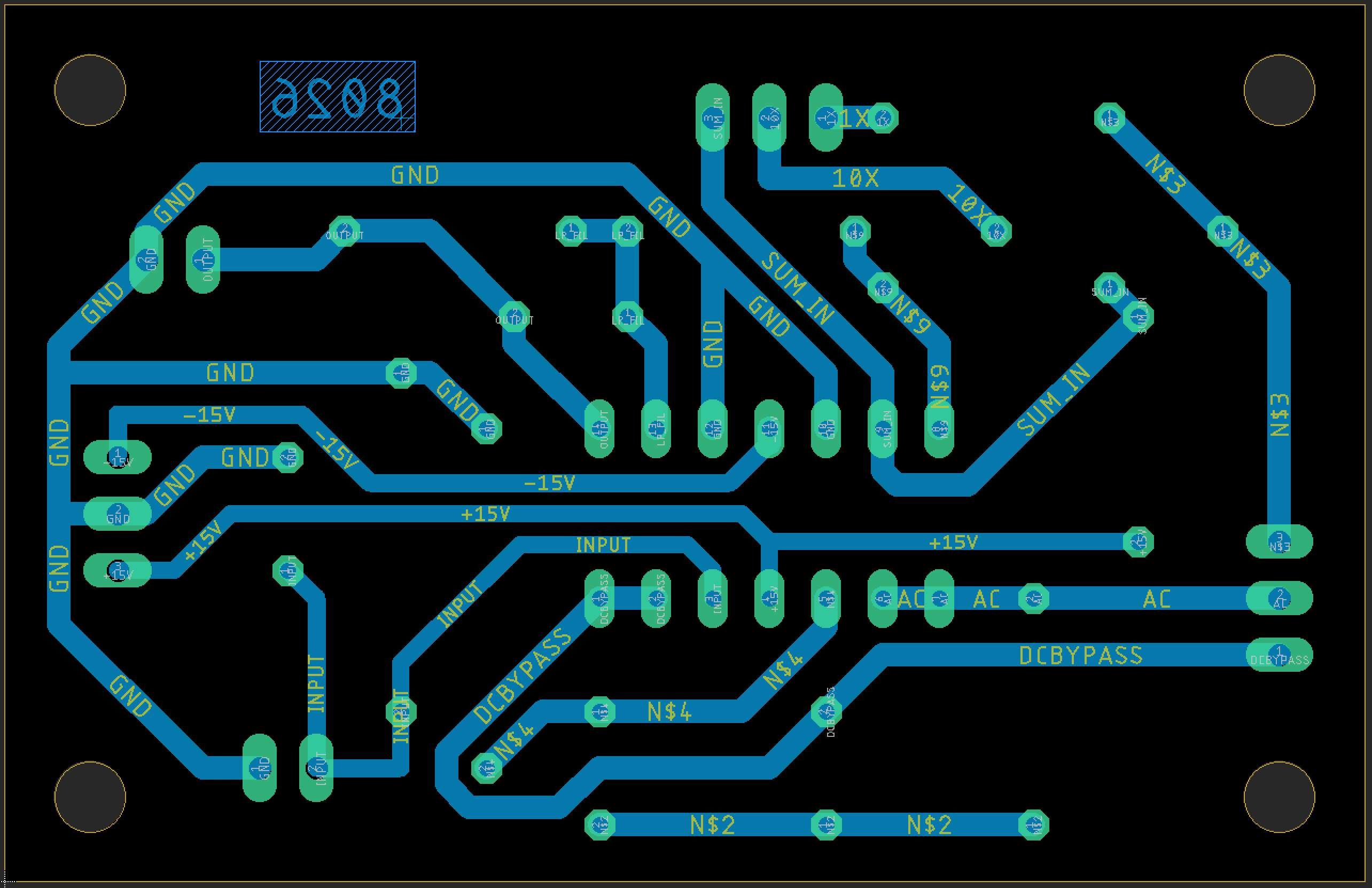
The importance of understanding of the prototyping process. By understanding how we were going to prototype and ultimately build our final design, we were able to tailor our designs to be easier to debug and assemble. For example, since we were using machined copper circuit boards (as opposed to printed ones) there were no plated through holes nor vias for signals. These had to be soldered by hand where needed. To avoid these operations I designed our boards to keep most connections on the “bottom” of the board where we would solder to, when a connection needed to be on the “top”, the trace would be terminated typically at the pin of some component rather than a via.
Detailed Report
This was a semester long project I worked on with another student. We were presented a specification outlining the desired performance characteristics of our final design which was a hobbyist oscilloscope based around an Arduino Nano to convert an either ±15 V or ±1.5 V input signal to a 0 to 5 V output to be read by the Arduino, complete with an adjustable trigger level and AC or DC coupling selection. In addition to creating a design that would condition the signal as required, we were tasked with documenting our progress and research in regular reports.
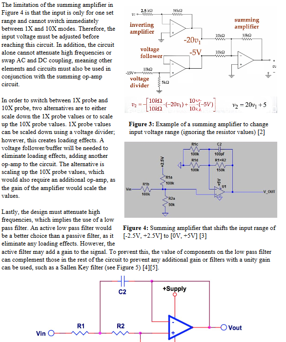
We began by researching existing circuits that achieved a something we needed and then combining these individual circuits and specifying parts to make proposed solutions. This began with schematics of our designs in SPICE software (PSPICE originally, then LTSPICE) and simulating them with different expected inputs and see if the outputs would be what was expected.
My teammate and I then refined our designs and decided on our proposed design before moving to EAGLE to design a circuit board for a prototype of the proposed design. Knowing that these boards would not have through-plated holes I designed for assembly by keeping all traces on the solder side of the board for the prototype.
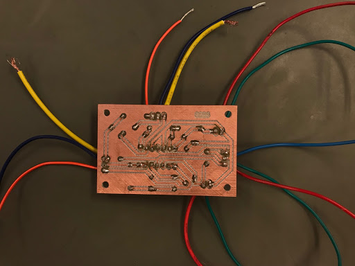
Once the boards were manufactured and we collected them along with our selected parts, it was our duty to assemble and test them using a function generator and an oscilloscope to verify our designs. Here are some photographs of the prototype.
Our tests were successful, however I made the mistake of misreading a label when gathering components which led to one of the capacitors being three orders of magnitude too large (1 uF instead of 1 pF), which resulting in our low-pass filter cut-off frequency being 20 Hz in tests instead of 20 kHz. This being a human error during assembly, did not require us revising our design to correct.
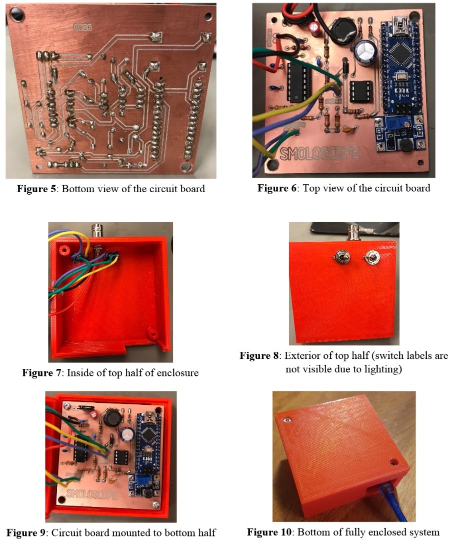
The final stage of the project was to add the Arduino and ±15 V power supplies for the op-amps to the board and design a 3D printed housing for the system. We used the suggested component values for the circuits except for the -15 V supply where we adapted a -12 V design to configure it to output -15 V. Below is the section of our final report displaying the system in different configurations.
This final design was also subjected to testing to verify its performance to the criteria specified at the start of the project. Our testing was partially limited by the equipment we had (namely the range being limited to ±10V on the function generators, preventing proper ±15 V tests). Our results were not perfect, however we deemed them appropriate given the expected use of this ‘product’ being hobbyists on low frequency signals.