Arbiter Lighting
Table of Contents
Overview
The team’s new tricycle needed lighting on it to make it road legal. I was tasked to prepare a system based off of what was proposed for Tempest (the previous vehicle) but never realized in time for its competition. This ended up becoming my first printed circuit board I would design and assemble!
Even though I did do some part selections and slight modifications, the system was still principally not of my own design, so I won’t credit it as my first complete PCB project, nor my first large scoped project without a microcontroller.
Requirements
- Provide a constant current to the LEDs of the bike
- Front, rear, left, and right light banks individually
- Allow the user to easily control the lights as needed while riding
- Blink the turning indicators when used at a frequency of about 1Hz
- Run using a nominal supply voltage of 11.1 V
Objectives
- Minimize wasted energy
- Have a highbeams bank for high-power LEDs
Takeaways
- The project was pretty simple looking back but exposed me to many new concepts for me, namely the concept of using MOSFETs in non-saturation (linear) operation modes.
- This was the first time(!) the team had proper lights ready in advance of the competition
- This was my first electronics project for HPVDT, and I would become the Head of Electronics following its completition and the departure of my mentor from the team.
- Running several parallel lines of LEDs significantly increases current draw and losses. Perhaps it would be better to raise voltage?
Detailed Report
The basic units of this design were descried the year prior in a nice PDF document for Tempest (available on the team’s GitHub for it, here. It was my job to slap four of these onto a circuit board with the supporting electronics and have it ready and installed before competition in April.
Designing the Circuit
The basis of the circuit is a MOSFET constant current circuit similar to (a) in the figure below, with one used for each line LEDs. The basic fuctional principle is that MOSFET’s gate (Q2) is initially pulled up and it begins to allow current through the LEDs into the resistor, R3. As the current increases so does the voltage across R3 until it passes the threshold for the NPN transistor, Q1, to begin allowing current to flow across it as well. This pulls down the voltage on the MOSFET’s gate until the current decreases enough through Q2 that Q1 stops pulling it down any further. This balance is set by R3’s value so it determines the current supplied to the LEDs.
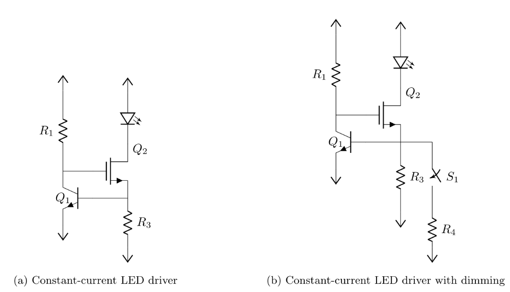
Other than changing some parts due to availabilities of the transistors origianlly mentioned in Tempest’s outline, and then some of the resistors to compensate for the different characteristics of these new transistors, the design remained fundamentally the same for these into the final design
There was also a design in the outline, instructing how one could use a 555 timer IC to generate the regular pulses needed for the turn indicators, so I followed this design without any modification needed. Looking back, the 555 is a perfect choice for this due to the fact it could operate in the system’s power domain of 11.1 V with no regulators of level shifters needed.
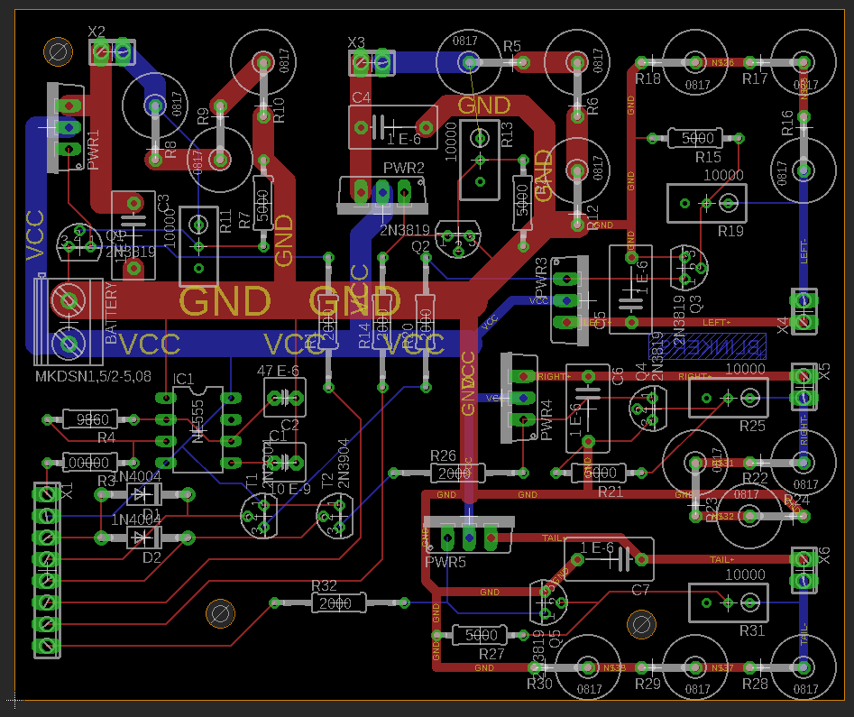
With these subcircuits designed and connected, I moved to prepare the circuit board using EAGLE. The first step was to prepare a schematic in EAGLE, which was not too difficult once I learned how to navigate the part library propely. Afterwards I began laying out the circuit board. Given the high currents going through the system (if all lights were on simultaniously, more than 10A would be drawn!) I increased the width of the main power traces accordingly.
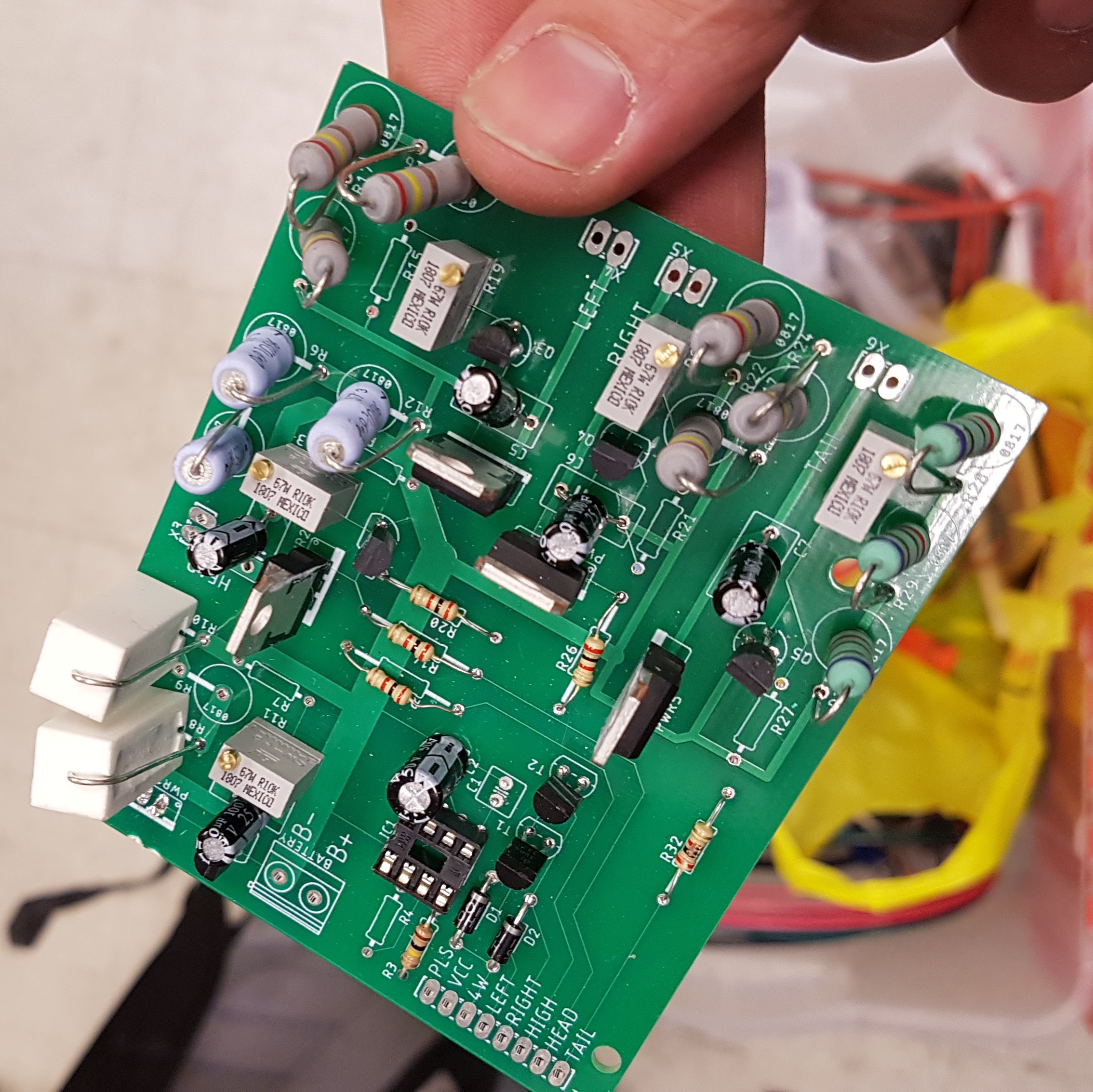
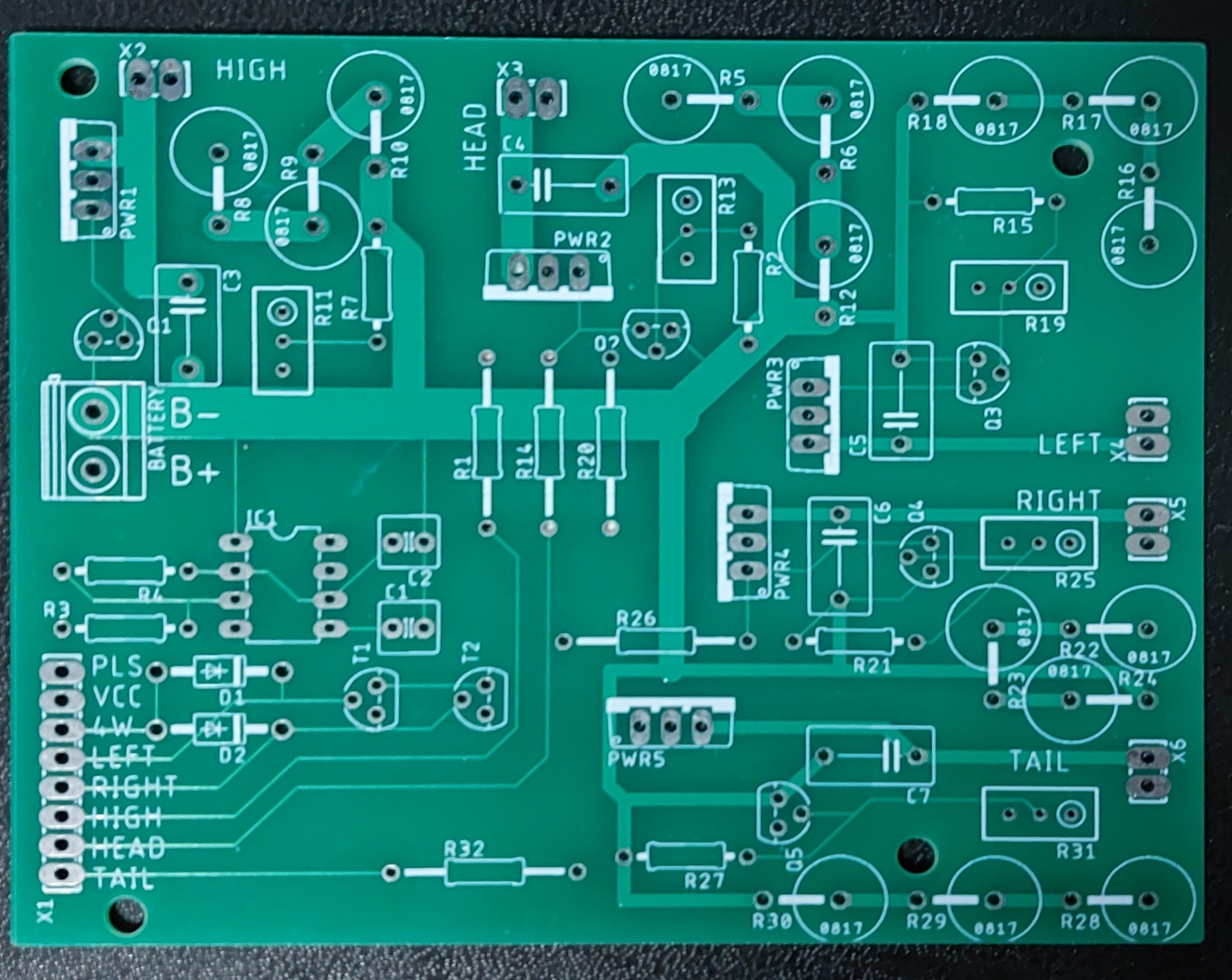
Once produced the finished circuit board looked like this, with that classic PCB green.
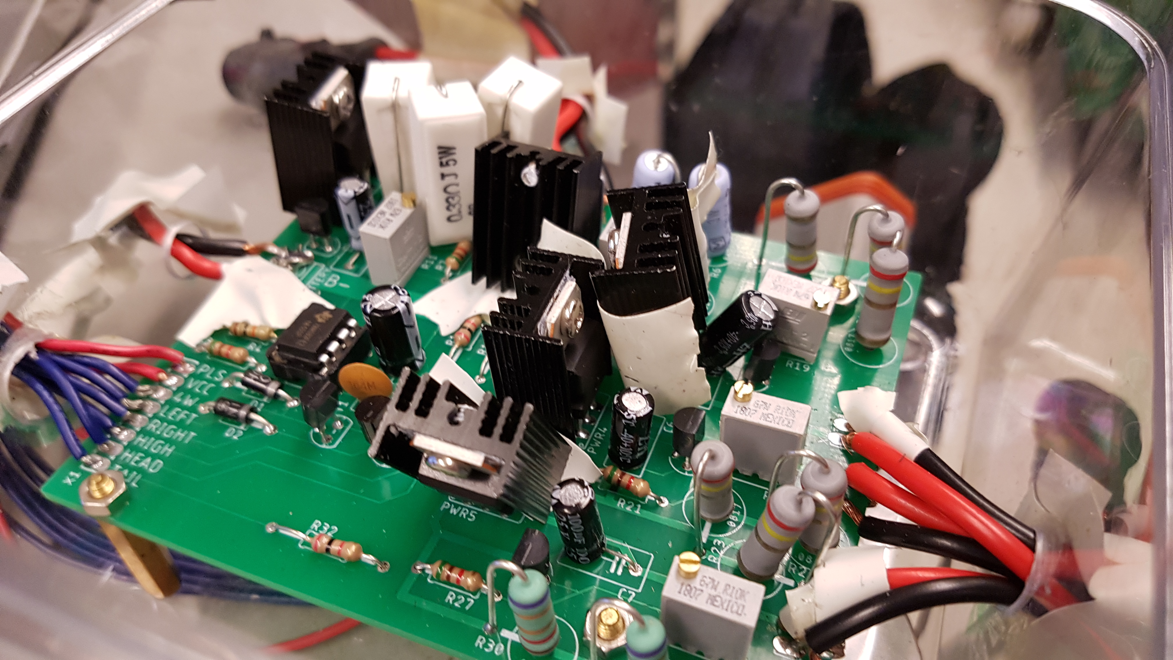
Assembly
Assembly wasn’t anything particularly complicated. It was an entirely through-hole board, composed mostly of high power resistors and transistors so there was lots of space for me to solder and not worry about creating shorts. Although it may appear as though the board is held in the vehicle due to its soldered on wires, there were connectors present on these wires that would allow the system to be easily removed as needed.
A partially assembled spare board was prepared should the need arise, however it never found use as more than a paperweight.