Scoreboard
Table of Contents
Overview
For the Tools 102 event hosted by the Blue and Gold Committee to help teach students how to use tools and build a fun little project, I offered to try and develop some electronics to help keep score for their game of pool.
The system was simply meant to keep track of time elapsed and the number of balls sank using light interrupts. Displaying this information and ringing a buzzer if they failed to clear the play field in time.
Although I learned a lot related to the use of timers in microcontrollers, the system didn’t end up getting used due to other electrical issues present such as the sensors being unreliable and poor connection quality.
Requirements
- Display count of balls and time remaining
- Accept input from two light interrupt sensors
- Operate buzzer when game is won or lost
Objectives
- Play a nice little tune instead of a static buzz
- Display more messages (e.g. “Welcome”, “Play ball”, etc.)
Takeaways
- Your data is only going to be about as good as your sensors
- Not even great sensor fusion can polish a turd
- Timers are a very cool feature on microcontrollers
- Writing directly to registers saves a ridiculous amount of time
Detailed Report
To contribute to the Tools 102 event hosted by the Blue and Gold Committee to help teach students how to use tools and build a fun little project in the process, I offered to try and develop some electronics to help keep score for their game of pool.
My job was to focus on the score-keeping system since there would be others that would work out the sensors as part of the mechanical design.
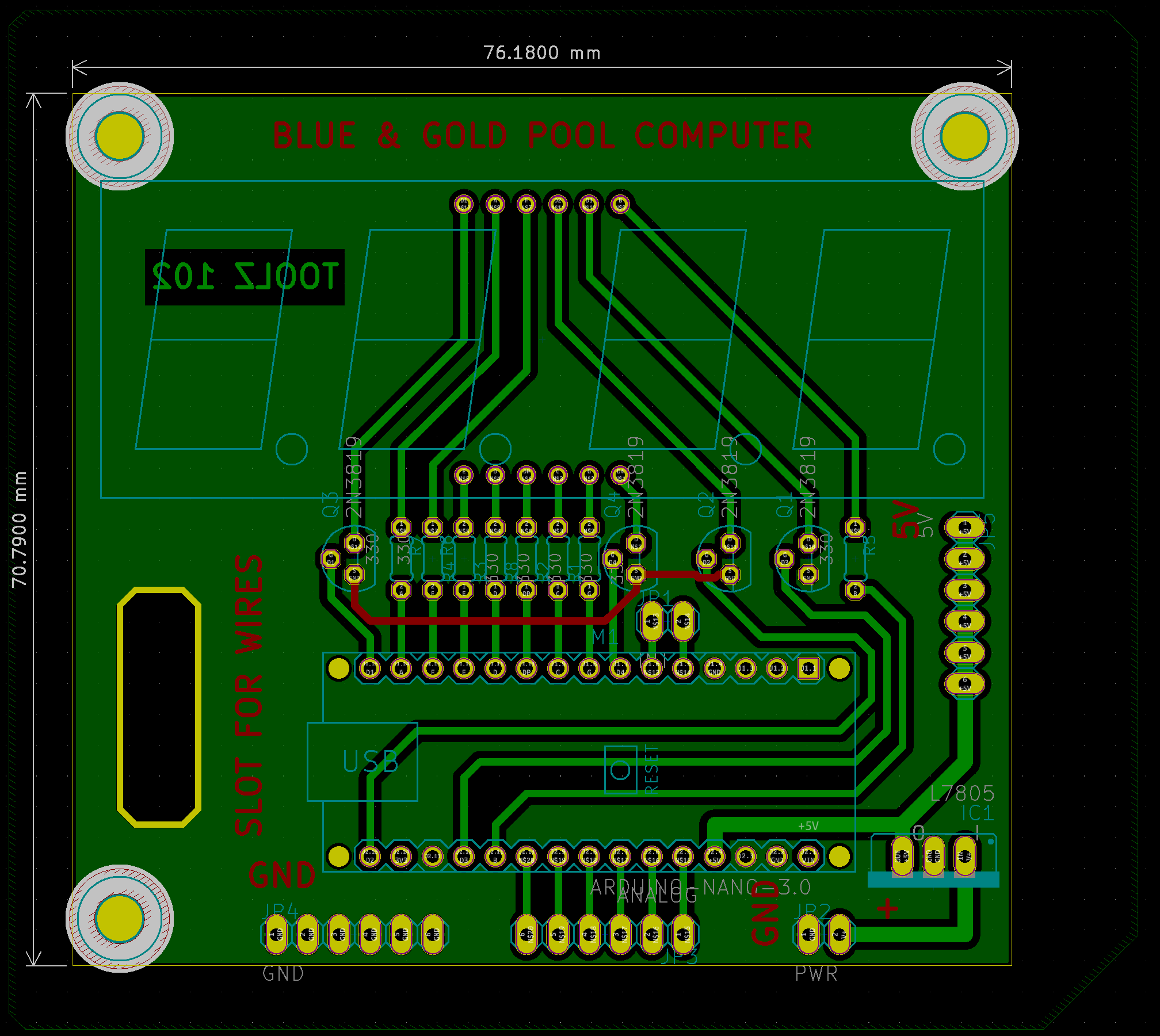
Note: this project’s hardware was originally done in EAGLE. I have simply imported the files into KiCad to generate the figures used in this article.
Circuit Design
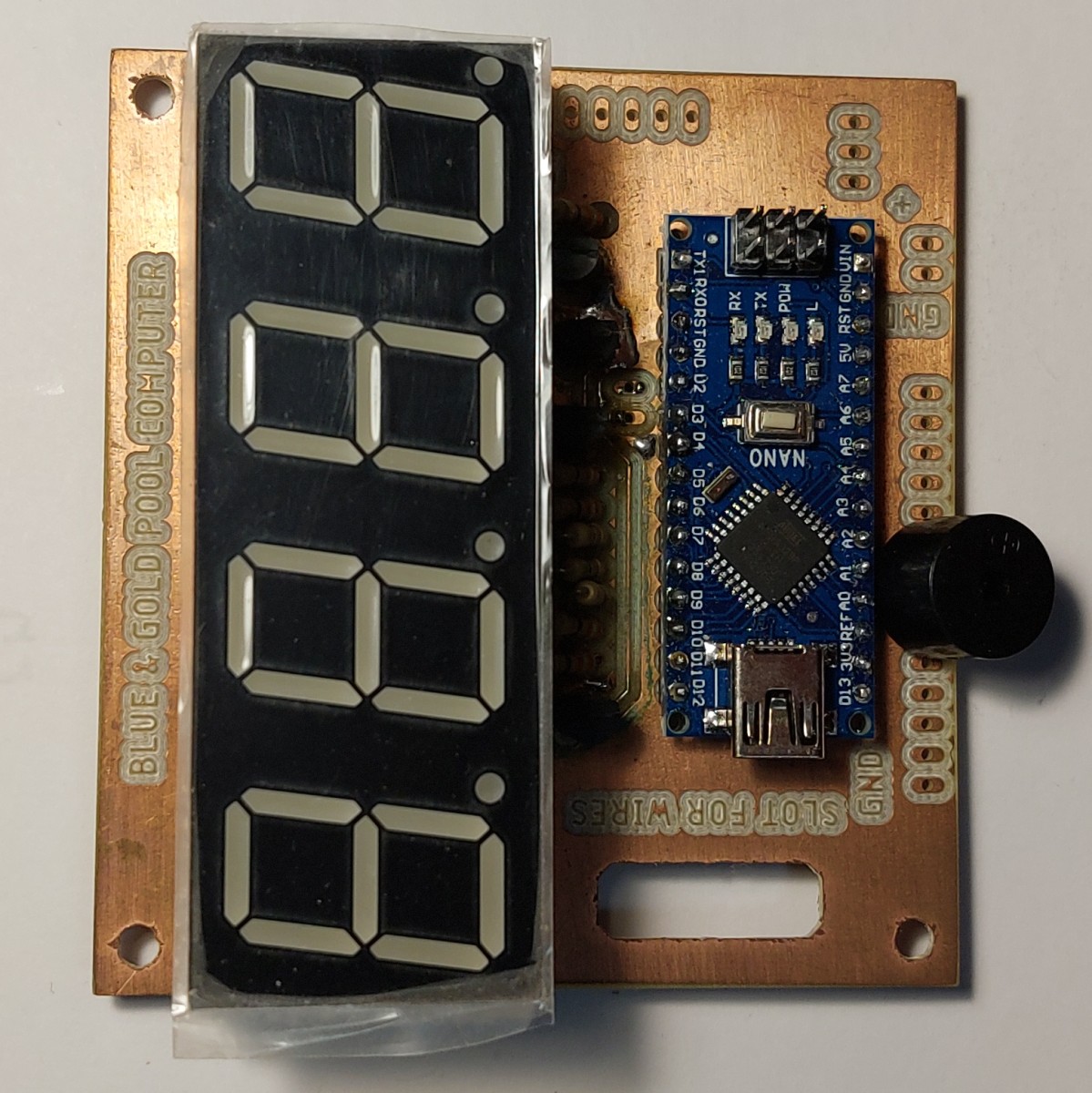
The system was pretty simple, an Arduino Nano would be soldered to a board what held the hardware needed for the display as well as a voltage regulator and breakouts for future inputs/outputs.
The display used was a four digit, 7-segment display that needed each of the common cathodes for the digits to be controlled so digits could be multiplexed. For this there was a current limiting resistor between each segment pin and the control pin on the Arduino and a MOSFET to control each digit.
For general purpose inputs/outputs for the Arduino I made two sets of headers, one with the two interrupt pins on the Arduino and another with the remaining unused pins. It was actually one of these headers that I used for the buzzer since that was an we had after I had the boards made! I also left several pins to connect external systems to the power lines of the scoreboard.

Layout
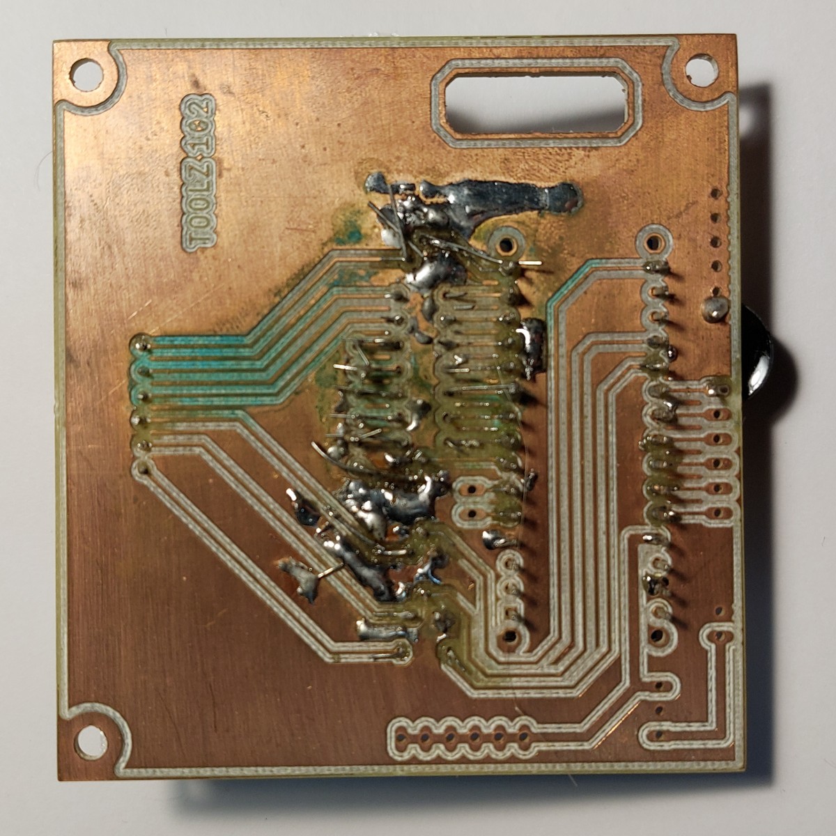
The layout was a similarly simple affair. The challenge arose from the fact that routing everything on the rear of the boards was proffered because the boards were going to be milled on campus (not printed) so there would be no through-plating to easily connect signals across board faces. Thus to connect a signal from a trace on the top to a pin, one would need to solder on the top side, between the part and the board - no easy feat especially in a crowded board. So having as many traces as possible connect to parts on the bottom and stay exclusively on the bottom of the board would greatly simplify the assembly of the board.
Since it wasn’t going to get printed, there was no silkscreen available to use, so I put my board notes on the copper layers.For example the instruction to loop the wires soldered to the board through the hole on the left of the board so any pull on the wires wouldn’t stress their connections.
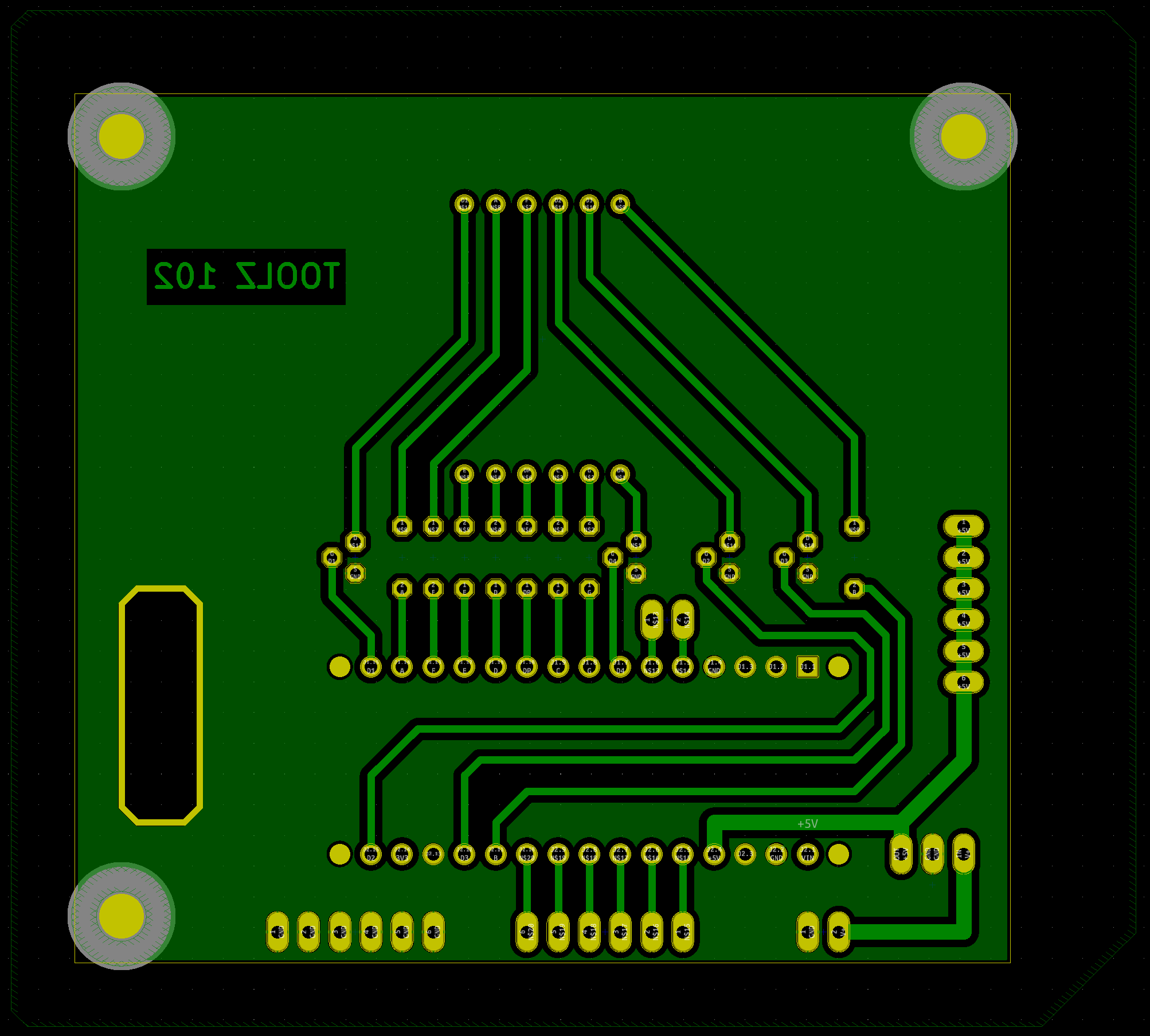
Large non-functional pours of copper were left on each side to minimize the milling time of the boards.
Other than a single trace to bringing a ground connection between the display MOSFETs, there are no electrical connections on the front.
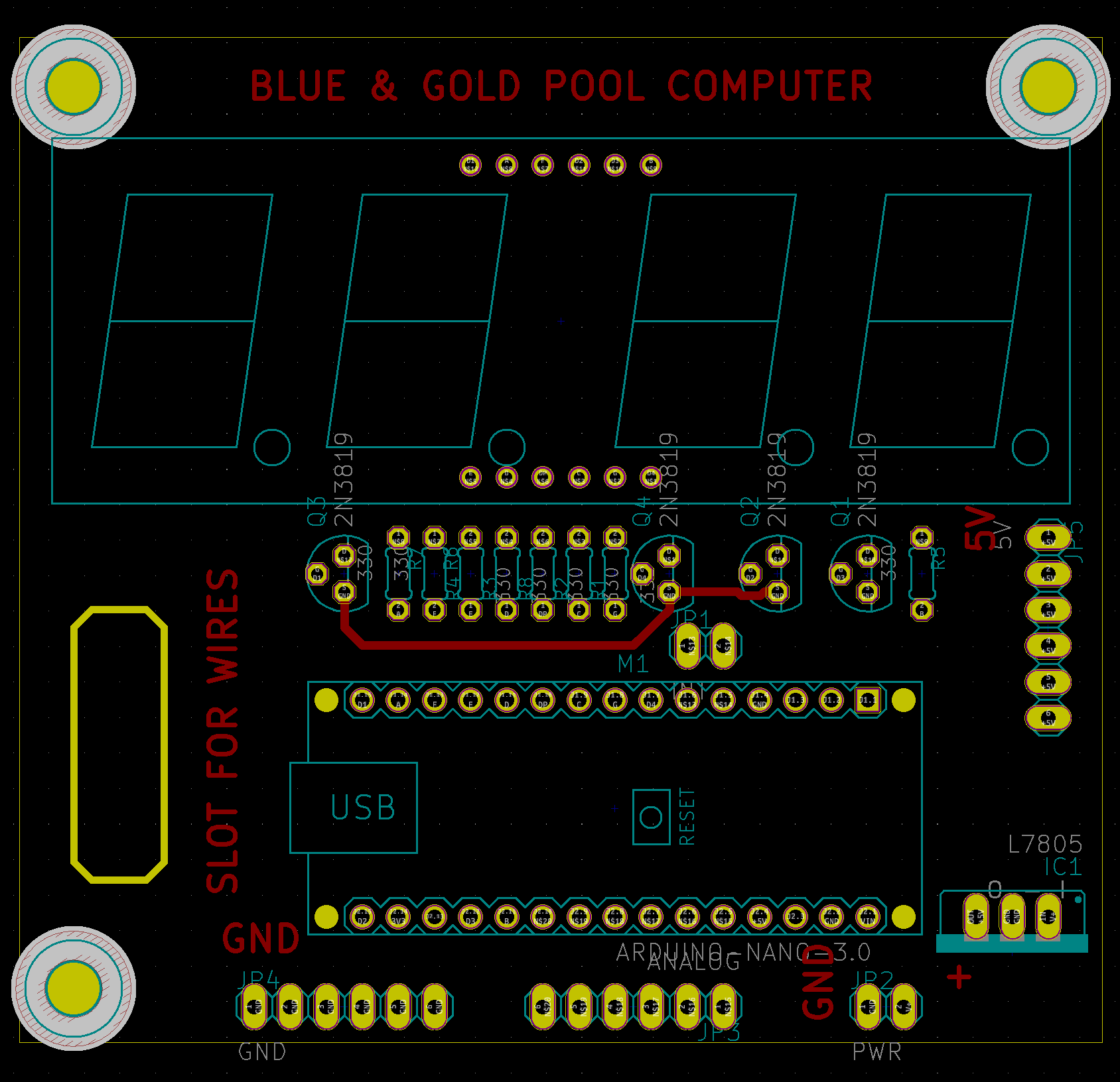
The vast majority of connections were formed on the rear with effort put in to place components to simplify traces.
Assembly
Assembly unfortunately wasn’t as simple as expected. There were three main issues in the assembly process, in decreasing severity:
- Display pin holes were undersized when machined
- Top MOSFET ground trace was over-machined and this broken
- I undersized the length of the resistors (purely an aesthetic issue)
The main issue that immediately arose was the fact that I undersized the holes for the display’s pins so it wouldn’t fit where it was meant to. Eventually with the help of a friend we got around this issue by soldering cut resistor leads to the pins of the display and then soldering those to the board since they fit the holes. Since the display had to hover above the board we stuffed some foam between the board and it to support it and avoid stressing the pins.
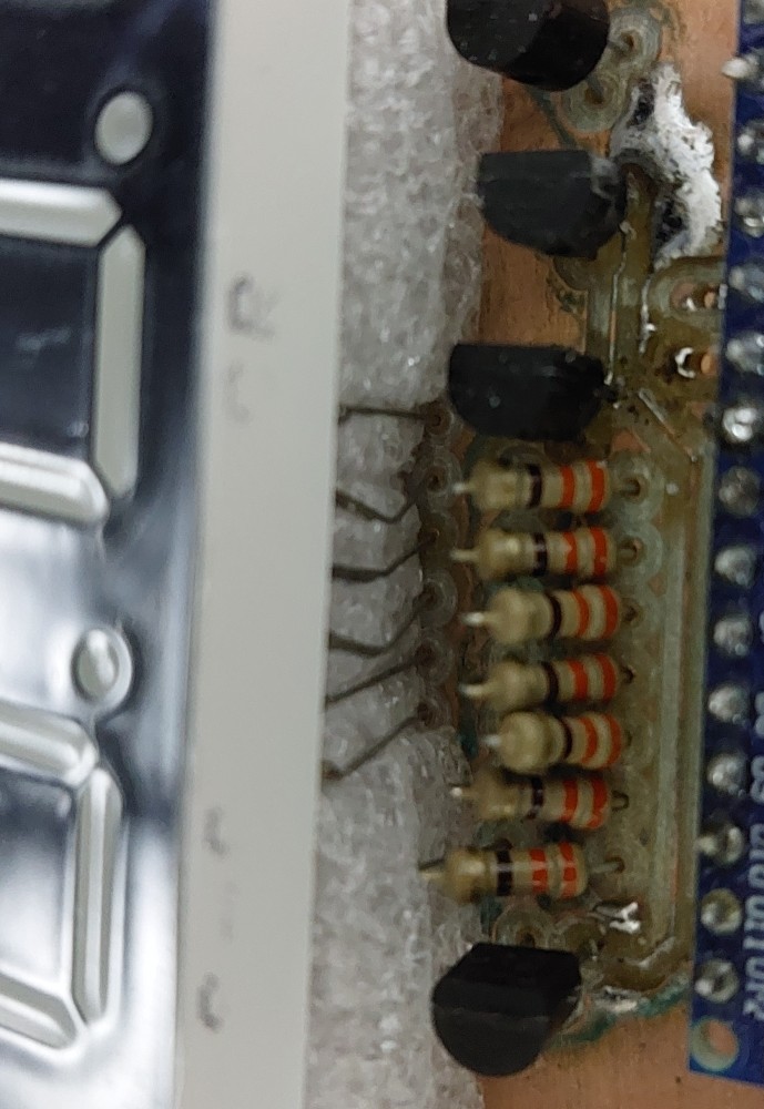
It is pretty visible in that figure that the resistors aren’t sitting nice and flat on the board, although I think it gives them some nice charm to rise up at a 45 degree incline.
To address the broken ground trace for the MOSFETs, I repurpaced the previously isolated copper pour on the back and made it into a ground. Then I used the terminal leads of the MOSFETs to reach and connect to the pour, as well as adding a few bridges between orphaned pours.
Coding
The coding for this project was done entirely in the Arduino IDE. The general flow was that the players would press a button to start the countdown and begin playing. As they played the screen would alternate between showing the time left and the count of balls remaining in play. Once either the time ran out or they sank all the balls the system would ring a buzzer and display the time left if they won as a score. It would record the score to non-volatile memory if it was a new high score.
The inputs were all meant to be digital, from the start button and the ball counter(s). So even as interrupts they were not really interesting or difficult to code, as was the general loop of code to keep track of time and ball count. The real meat of this project’s code was the code to display information to the players.
Display Code
My original approach to multiplexing the digits and displaying characters was to simply use a periodic function in the main loop to display a different digit every few milliseconds. However, this quickly ran into issues when I added other code especially the buzzing that would take control of the loop for a notable period of time and the display would be noticeably frozen on a single character.
Looking around for a solution to this I found some guides on how to use timers and periodic interrupts for exactly this, which seemed to be exactly the ticket out of this.
The premise of timers is that they run in parallel with the rest of the system, counting up and once a threshold value is struck, a specific interrupt function takes temporary precedence over any other operation and is run. So I set one of these up to run at about 500 Hz and display a digit so the display would be refreshed at an effective 125 Hz.
This needed me to set up some code and use registers to configure the timer. I used timer 2 since I read the documentation and found that timer 0 and 1 were being used for keeping track of time with millis() and buzzer functions which I did not want to interfere with.
  // Reset timer 2
  TCCR2A = 0;
  TCCR2B = 0;
  TCNT2  = 0;

  // Set compare match register for 500hz increments
  OCR2A = 90; // = (16*10^6) / (1024 * freq) - 1 (must be <256)
  TCCR2A |= (1 << WGM21);   // turn on CTC mode (Clears on timer compare)

  TCCR2B |= (B111 << CS20); // Set CS20 and CS22 bit for 128 prescaler
  TIMSK2 |= (1 << OCIE2A);  // enable timer compare interrupt
The timer interrupt function itself was a basic void() function in essence, but declared as an “Interrupt subroutine”, or ISR for short, specifically for the timer 2 compare A event.
ISR(TIMER2_COMPA_vect) { //timer2 interrupt, displays a character on the display

	...
	*code*
	...

}
Although this did work, the rest of the system became very sluggish. This was due to both the frequency and duration of these interrupts combining to occupy the majority of the chip’s runtime. I felt that I could do work to reduce the duration of these functions instead of sacrificing refresh rate (even if 125 Hz might be excessive).
In the original code I had for the interrupt, it would essentially go through a loop of all eight segment pins individually. Each iteration would have the microcontroller extract the needed state for that pin from a byte, then go and use the standard digitalWrite() function on said pin before going to the next. I figured if there was some way to speed this up, ideally by bypassing the digitalWrite() with something less abstract and/or removing the loop I could save significant time.
I managed to achieve both these goals by using look up tables and writing directly to the output (port) registers! On the Arduino (and most other microcontrollers) pins are grouped into “ports” which are controlled using registers one can read or write to in code. This is what Arduino and many other languages help the user by abstracting, although it costs performance. Using registers directly allows one to bypass the abstractions saving time per pin. Not only that but because each register affects all the pins on a port, it allows multiple pins to be modified with a single instruction, thus addressing both my desires in a single swoop!
I reworked my code to make use of registers and an array of lookup tables for each port. These arrays would store the settings needed to show a specific character’s segments (e.g. “A”) given the character code in displayedChar[], and the digit, currentDigit.
ISR(TIMER2_COMPA_vect) { // Timer2 interrupt, displays a character on the display
  // Display
  // Turn off all digits and segments
  PORTB &= portBClearMask;
  PORTC &= portCClearMask;
  PORTD &= portDClearMask;

  // Turn on required digit
  PORTB |= portBDig[currentDigit];
  PORTC |= portCDig[currentDigit];
  PORTD |= portDDig[currentDigit];

  // Set segments
  PORTB |= portBSeg[displayedChar[currentDigit]];
  PORTC |= portCSeg[displayedChar[currentDigit]];
  PORTD |= portDSeg[displayedChar[currentDigit]];

  if (currentDigit == 3) currentDigit = 0; //Reset
  else currentDigit++;
}
Testing
Doing unit tests of my system done by simulating input by shorting pins with jumpers, was all successful. Unfortunately our issues with the unit tests of the sensors were failing so we never got to do a full test.
Overall
I am confident it would have worked as intended in the larger system if the sensor issues. Alas given the nature of the event, time was in short supply so the focus was shifted to at least having a completed pool table over a partial one with a working score system.
So this got cut from the build partway through the night and I kept the board ever since to fool around with the display some more.