Zephyr
Table of Contents
Overview
For the Human Powered Vehicles Design Team’s (HPVDT) 2019 entry to the American Society of Mechanical Engineers (ASME) human powered vehicle competition I was tasked as Head of Electronics to produce an electronics system to control the lights as well as collecting and displaying data to the rider.
This was achieved using a custom circuit board I designed in EAGLE that housed an Arduino Nano on the bike which communicated with a mobile phone over Bluetooth to transmit data for the rider to see as well as receive commands from the rider (for example “turn on the left indicator”).
Requirements
- Have all the lights required to be road legal
- Front and rear lights to be continuously on
- Left and right turn indicators that blink (at a rate of roughly 1Hz)
- All lights need to be controlled by the rider
- Collect and display the following data to the rider
- Bike speed
- Cadence (rate of pedalling)
Objectives
- Reduce power wasted for lighting
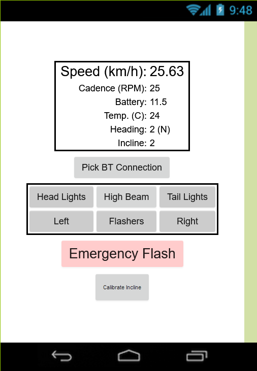
- Use a mobile phone app for the primary user interface
- Have a high-power mode for the front lights to act as high beams
- Collect and display the following data to the rider
- Ambient temperature
- Heading (compass)
- Incline
- Battery level
Takeaways
This was my first circuit to use surface mount parts, as well as switched mode power supplies (used to drive the LEDs). Both of these introduced me to new and more efficient ways to utilize space and power respectively, and the challenges that need to be overcome to utilize them. For example the selection of passive components for the LED driver can drastically change the performance of the system.
This was also my first foray into making a mobile app, even with the help of MIT AppInventer to aid me. Using a mobile phone was a novel way of communicating with a system and pleasant to get all the data displayed to the rider in a clear manner. I could also easily reconfigure the display with feedback. However issues with using the phone mid-ride as well as occasional communication interruptions make me question the true feasibility of re-using this interface in future projects for HPVDT.
Also learned to double check project names before committing to them, to avoid errors such as using “Zypher” instead of “Zephyr” in project materials.
Detailed Report
As electronics lead it was duty to develop the electronics system for our annual entry in the American Society of Mechanical Engineers (ASME) human powered vehicle competition. Although the power that propels the vehicle must come from the rider(s) electronics are used extensively in secondary systems; such as collection and processing of vehicle data (e.g. speed) and lighting for safety (these lights are akin to a road-legal vehicles).
Until 2019 the team did not have any custom system for this, relying on off the shelf lights and speedometers, except the previous year I managed to design a custom lighting circuit board which would allow us to properly drive the high-power LEDs we use for lighting by maintaining a constant current through the connected load. Looking to iterate on it for Zephyr I concluded it required significant redesign for two main reasons: size and efficiency.
Lighting Design
The issue of size and efficiency were solved with a transition from using simple (resistors and transistors) through-hole components to regulate the LEDs to a switching mode power supply composed of mostly surface mount parts. This raised the maximum hypothetical efficiencies from 65% to over 90%, while also reducing the footprint of the lighting system by a factor of three.
Before I fully committed to this new lighting approach, I purchased the components required and had a preliminary set of circuit boards milled for prototyping. One which was the simplest configuration required by the power module, and another more complex one which using a potentiometer and some jumpers allowed the current setting to be adjusted without replacing any components.
Testing Lighting
These were then assembled and tested. They both performed as expected and were able to deliver upwards of one amp to LEDs with incredible line regulation resulting in now current fluctuations over the expected input range. Line regulation is important for this system as the bike is battery powered so the voltage supplied to the system will vary between 12.3V and 9.9V over a battery discharge cycle.
In addition to driving LEDs with a constant current, a regular pulsing signal of approximately 1Hz was needed for the turn indicators, this was achieved using the 555-timer configuration used in the previous year.
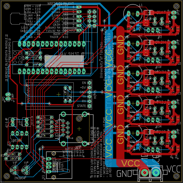
With the performance of lighting system verified, I proceeded to initiate the designing our final PCB by putting five identical LED driver circuit to operate in parallel to drive each different set of lights (head lights, tail lights, high beams, left/right indicators) along with the timer circuit.
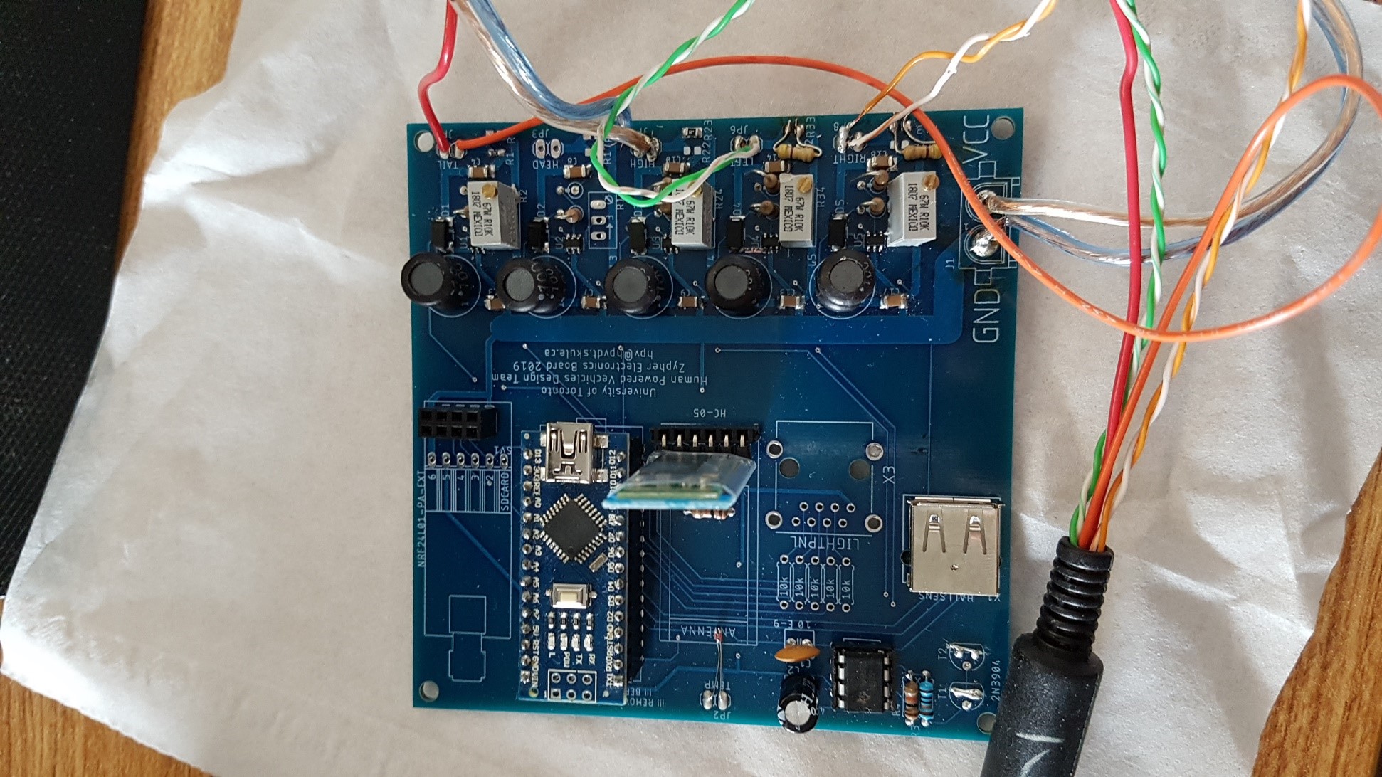
System Design
The remaining PCB space was allocated to data collection and processing, at the heart of this sat a removable Arduino Nano which was responsible for polling sensors for data. The data collected and the collection method are listed below:
- Speed of bike – Using a Hall effect (magnet) sensor to trigger an interrupt every time a magnet on the wheel spokes passed it.
- Cadence (pedalling rate) – Gathered the same way as speed, but monitoring pedals
- Temperature – Resistor voltage division where one resistor is a negative thermal coefficient thermistor
- Battery level (voltage) – Resistor voltage division (this is to reduce the input at peak battery level (12.3 V) to be tolerable for the Arduino to read (<5 V))
In addition to being connected to sensors, the Arduino was also connected to the controlled the enable pins of the LED drivers, allowing it to control the lights, which could be dimmed using PWM signals.
There was space allocated to three other removable modules on the PCB: a microSD card reader for data logging, a Bluetooth module (an HC-05) to communicate with the rider’s mobile phone and long-range communication module (an nRF24L01+ transceiver) to broadcast this data out of the bike. Of these three only the Bluetooth module was extensively used, due to the necessity of the bike communicating to a phone to be operated. The SD card was neglected after it was discovered that logging could be performed just as easily on the phone, the long-range communication was not implemented as it is meant to be used for a research project for me over the following summer.
Assembly
The board assembly was a new experience to me. It was my first time soldering surface mount components other than the protoboards for lighting. I soldered it entirely by hand with no stencils. For a first job I think it went alright. Looking back on it now, I can see I’ve gotten better with time, and stencils can go a long way to making a nice board.
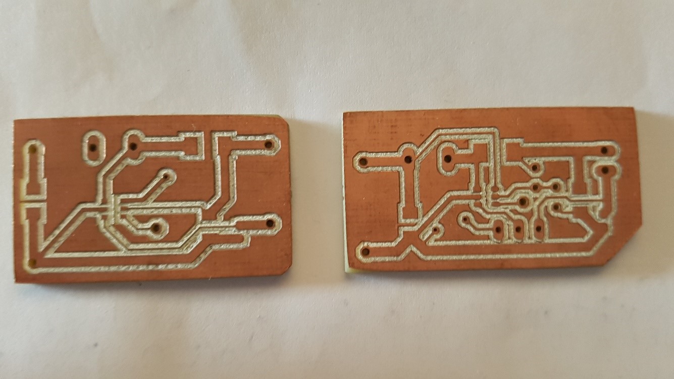
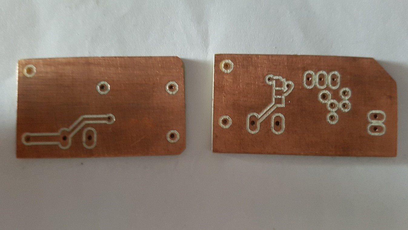
Contingency Board
I actually had concerns over whether or not the printed circuit boards would make it in time, so I had a different design made on campus using the board milling machine to use as a backup should they be needed.
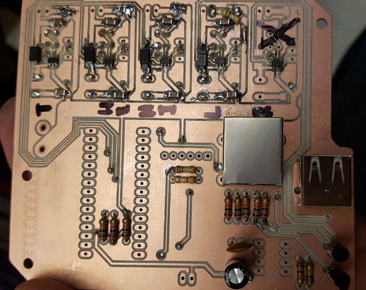
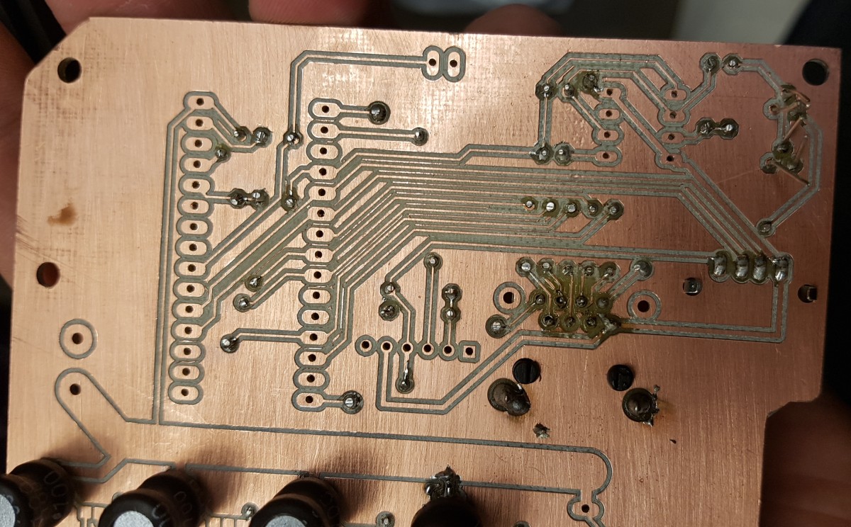
Since the proper boards arrived just in time, these were never used.
Outcome
The Zephyr system worked at competition. Unfortunately it didn’t get much use, since there was no dedicated phone for the app so the one teammate with an Android phone needed to lend their phone if it was to be used.