Force Feedback Tester
Table of Contents
Overview
I expanded my force regulation system from just the single axis of feedback needed on the kneeload robot project from my previous term as a co-op student at IGB, to controlling up to six axes of force (three linear force, three torques) so the company could perform ingress-egress tests using a robotically manipulated mannequin.
In addition to being able to control these additional axes, I also improved the configurability of my tester, allowing the use of specifically formatted text files to determine the forces needed at each point of the test cycle. This made it easier for test technicians to operate and customize the test protocol to each client’s needs.
This is still my largest design project have done for work.
Requirements
- Regulate the force on six axes
- Three linear forces (\(F_x\), \(F_y\), and \(F_z\))
- Three torques (\(T_x\), \(T_y\), and \(T_z\))
- Implement this on the existing KUKA robots on site
- Train test technicians to operate the completed system
Objectives
- Improve system documentation
- Enable the use of configuration files for tests
- Improve the communication speed between the robots and the computers
Takeaways
This was by far the largest and most complicated LabVIEW project I had developed to date and exposed me to many concepts I had not yet encountered coding in general. The concept that I spent most of my time on was the user input feature, as it had to recognize all sorts of user tomfoolery and then cope with it, preferably in a constructive way for the user.
Modularizing the system’s code enabled me to easily and rapidly scale it up from regulating just one to the six forces I needed.
Although my communication protocol works as needed, using more purpose built hardware for data exchange would certainly increase the bandwidth and thus decrease cycle times.
Detailed Report
This was the focus of my second time working at IGB Automotive. This project focused on implementing force feedback routines into old refurbished robotic arms to have them administer durability tests. This was built off some of the work I did the previous summer I was there, implementing a much more basic system.
The robots had to follow paths that were defined by the clients, with set points that were expected to administer a desired force on the seat, for example 500 N downwards on the cushion, and repeat these cycles several thousand times. The problem with this is that the robots had no internal force feedback/adjustment system; they were designed to merely go from point to point. This meant that a robot going to a point may apply a force of 500 N the first dozen times, however as the seat deforms from this cyclic loading it may only apply 400 N at the same position in a few hundred cycles.
Therefore, force feedback was vital to the system as it allowed technicians to properly configure the robots before starting the test to meet these requirements and would allow the robots to self-correct their paths if force targets were not met mid-test.
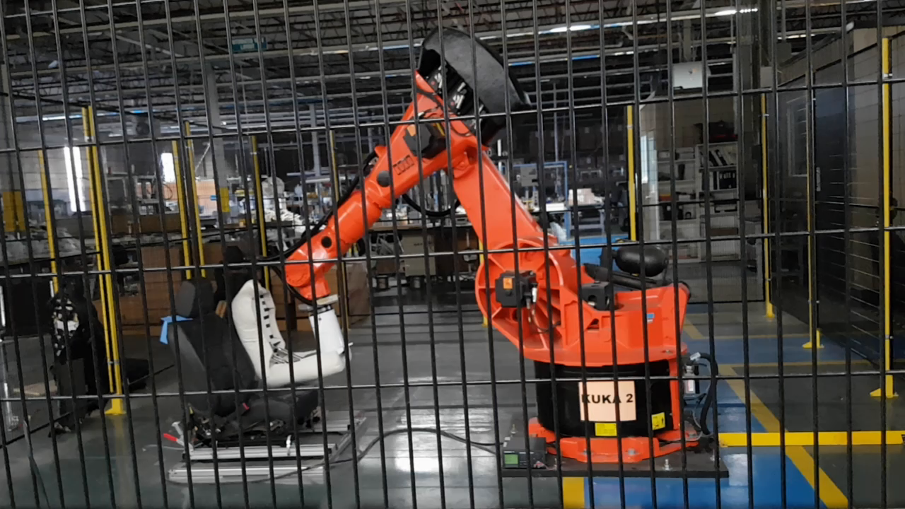
The Robots
There were two robots, each was equipped to administer a different type of test. One had a normal (single direction) load cell and was meant for applying forces at distinct points on the automotive seat using a hemisphere end piece (referred to as a ‘knee load’ test), the other was equipped with 6-axis load cell (X, Y, Z forces and torques) and an end piece to simulate a torso as it moves in and out of the seat (referred to as “Ingress/Egress” testing).
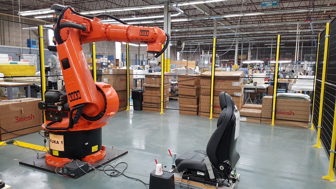
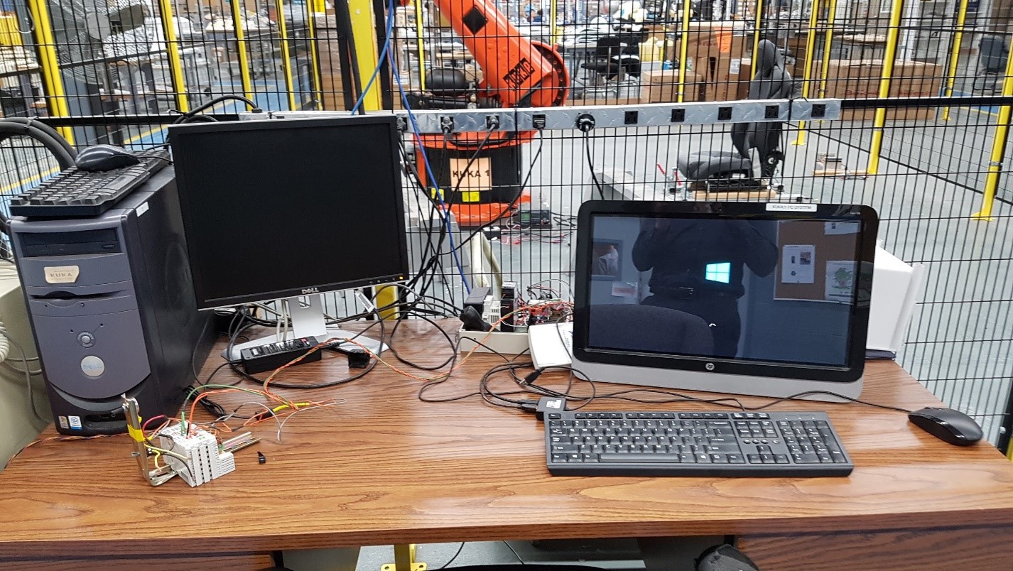
Other than their end-effectors, these robots were virtually identical. They were the same KUKA brand welding arm, used the same control cabinet and computer system, and had a ‘companion’ computer running LabVIEW to monitor and record data from the tests using the National Instruments data acquisition unit (DAQ). The reason for the companion computer collecting data instead of the robots’ own computer is due to the robots running a customized Windows 95 operating system with hardware from that era, making them incompatible of directly interacting with modern equipment and software.
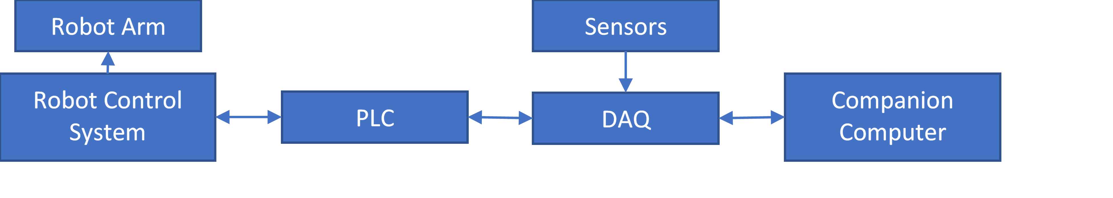
Establishing Communication Hardware
Reading into the documentation for the robots I found they had a programmable logic controller (PLC) interface that was still supported, that I could use to feed the robot data directly from basic analog sensors (like potentiometers which I used for testing) before connecting them to the DAQ to allow some basic communication between the robot and the companion computer. This led to the following system configuration for both robots.
System Software
With the hardware selected (binary input/output modules for the PLCs) and configured, I began the process of making software to run the system. This task was split into three parts: robot motion software, companion computer data processing, and communication between robot and companion computer. In working on this I worked to minimize the effort required by technicians to reconfigure the system for future tests.
Motion Control
The robot motion software was written on the robot control computer using KUKA Robotics Language (KRL), I learned and tested different command to achieve the ability to not only adjust the points mid-test (regulating load) but to also make it easy to configure the robots to new paths but only needing users to enter in the new points.
Data Processing
Data processing did not require much reworking to get it working at a basic level, the company already had some LabVIEW programs to monitor and record the force, I only added checks to see if the robot was meeting the required loading criteria to get a basic feedback system working. However, the test parameters were historically hard coded into the software which meant a different application had to be compiled for each different test. I spent a significant portion of my time rewriting the code so it could load in the test parameters using external configuration files made in Excel which made the system much more accessible to the technicians to configure.
Communication
The communication required work on both halves of the system (robot and companion computer). To transmit data between the two, I used a parallel communication system using the binary inputs and outputs on each half of the system. The reason for a parallel configuration was to maximize the bandwidth because the hardware used, the DAQ and PLC, were being controlled by software and thus were unable to respond and switch rapidly.
These extra parallel bits also helped keep the systems synchronized with a “handshake” that used one output bit on each side.
- (Both robot and PC handshake bits start low)
- PC sets its data outputs for the robot, then it raises its handshake output to high.
- Robot sees the PC raise its handshake output, reads in the data supplied by the computer.
- Robot sets its data outputs for the PC in response, then raises its handshake output high.
- PC reads in the data from the robot, then it lowers its handshake output to confirm.
- Robot detects the lowering of the PC’s handshake output and lowers its handshake.
- The process begins anew once another batch of data needs exchanging
Each step in this cycle took about a second or so because the KRL on the robots doesn’t have instructions to wait less than a second so that was the minimum timing I could used for these transfers.
Putting it all Together
The result of these was a system where the user would place a seat for testing, turn on both systems, select the appropriate motion program on the robot, select the appropriate configuration on the companion computer and run the test. Once the first few cycles were completed without issue the technician could leave the robot to perform the remainder unsupervised.
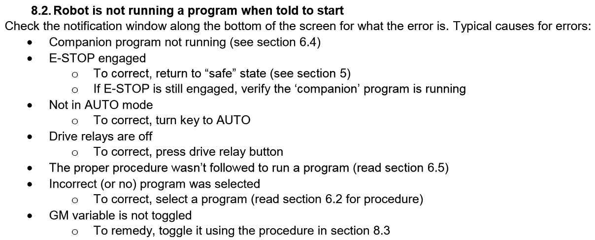
Throughout this project I was tasked with documenting my work and writing technical documentation for other to refer to in my absence. This included basic step-by-step instruction on how to perform basic operations with the robot and troubleshooting to advanced programming with examples.
Extra Media
Below is a video demo of the upgraded kneeload tester, I included a breakdown of the video as part of its description on YouTube so if you are very interested in it I would suggest watching it on their site.