Kneeload Tester
Table of Contents
Overview
My employer purchased a couple of robotics KUKA arms to administer loading tests to seats and although the KUKA robotic arms performed the motions perfectly every time, they lacked any internal feedback mechanism for regulating the force they applied. Thus after several hundred cycles the seats would deform and thus the robot would no longer apply the same force it did initially did when arriving at the same point.
I was tasked to, and delivered, in implementing a system for the robot to automatically compensate its motions to apply a constant force for the entire test (these could be upwards of 10 000 cycles) on their “kneeload” robot.
Requirements
- Use the robots as provided (e.g. no new control panel, robots, etc.)
- Enable the kneeload robot to regulate its force without human supervision
- Log all measurements to verify the performance of the system
Takeaways
- Interfacing with old electronics can be confusing, but playing around with the system until it works is a valid approach.
- Programming robot motions is easier than I expected
Detailed Report
My employer, IGB Automotive, was a manufacturer of primarily automotive seat heating and cooling units. As part of their efforts to improve their testing capabilities to improve and verify product quality they invested in robotic arms to deliver durability tests on their products to ensure continued operation over the life cycle of a vehicle. These tests needed a constant load to be repeatedly applied and removed from a seat at set positions, usually between 5 000 and 10 000 times, although some clients required more.
The Original System
The most basic of these tests was the “kneeload” test. It is designed to mimic the load exerted on a seat by the “above-average” (1.8 m tall, 85 kg, male) driver kneeing the seat as they reach behind the seat. To mimic this, the robot had a hemispherical end-effector, roughly 15 cm in diameter that was used to press into the seat at prescribed points.
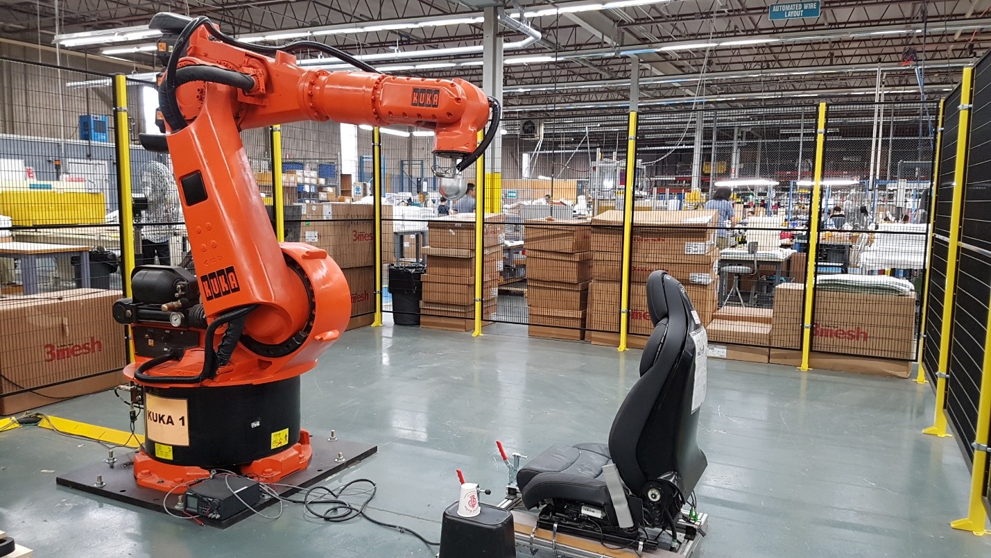
Although the robot could perfectly repeat the motions of a test cycle to the end of time, the seats would gradually deform during testing, so pressing 10 mm into the cushion would no longer yield a force of 200 N but only 150 N after a few hundred cycles which would not satisfy the testing criteria. The robot did have a load cell fitted to monitor the applied load by the end-effector, however it was monitored by a modern computer running a LabVIEW interface for the test operators completely separate to the robot’s control system based off a modified Windows 95 machine nested within the control panel.
(I remember when I was starting this project and my manager was working inside the control panel and explaining the robot to me. After mentioning the robot ran off Windows 95 he paused and poked his head out to ask me when I was born. “I was born ‘98 sir.” A quiet “Damn” trailed off as he went back to his explanation of the panel)
So although we were able to measure the force in real time, there was no feedback to the robot itself to adjust its motions. The system used by the test operators at the time was to periodically check if the force applied feel within or was soon going to drop out of specification - if so, the robot would be paused temporarily as the operator would then raise the seat by sliding some material underneath it and then fastening it down (you can see evidence of this above), before unpausing the robot to continue the test.
Closing the Loop
The missing link was communication between the modern computer collecting measurements and the robot control system. Once a bridge was formed, the matter of adjusting motions would be trivial and the robot could perform entire tests unsupervised.
Getting data in or out of the computer was pretty simple, the data acquisition unit (DAQ) we used to collect the applied force from the load cell had several unused general purpose input/output (I/O) pins so we could use them without needing to bring in new hardware or reworking the code significantly.
Getting data in or out of the robot presented issues though. There was no available I/O other than those used to trigger an emergency stop, built into its control panel. Any such I/O needed to be provided by an external programmable logic controller (PLC) connected to it. This was identified before I joined the team and they had some PLCs they expected to work with the KUKA but had not yet tried.
Playing with PLCs
I read into the specification of both the robot and PLC to verify how to connect them using the DeviceNet protocol they both supported. Once I had spliced the cables I needed for data and power I connected them and checked the status of the system using the status indicator on the BECKHOFF PLC I used to verify everything was correct.
Unfortunately the company did not have the software and hardware required to configure the PLC on hand for me so I had to deduce the default configuration of the PLC and how to interact with it using the documentation provided and a few tests. The only PLC input module I had available to me at first was a two channel, 0 to 24 V, analog to digital converter. So for testing I used a potentiometer to swing the voltage between extremes and see what needed to be done to get the robot to read and react to it.
Eventually after deducing some parameters I had the robot successfully swing either to the left or the right depending on whether the analog voltage reading I was feeding it fell above or below a threshold defined in the robot’s code.
This was the breakthrough we were looking for and made me really happy to just sit there fiddling with the potentiometer and watching the robot react accordingly.
After replacing the potentiometer with a digital output of the DAQ I was able to have the computer operate the robot just as I had with the potentiometer.
Making a Proper System
With the communication system proven to work, I had succeeded in making the bridge we so desperately needed. My work now turned to fleshing the system out and using it to implement motion adjustments.
The first order of business was getting more I/O for the robot side to allow more more data transfer between the computer and robot. For this purpose I requested two digital modules that worked at 5 V and the power module for them. One module provide dual outputs for the robot other dual inputs, and since they operated at the DAQ’s operating voltage of 5 V I could directly interface them. Using digital I/O also simplified coding on the robot since I didn’t need to compare values to arbitrary thresholds to make decisions.
As I waited for their arrival I worked to design a basic feedback protocol for the robot using the DAQ and LabVIEW for the robot. The basic scheme was that the robot would request feedback by toggling one of its outputs, then the DAQ would use two of its outputs to instruct the robot one of the following:
- (00) - No feedback ready (robot waits)
- (01) - Increase force (robot increments forward, checks for feedback again)
- (10) - Reduce force (robot retreats slightly, checks again for feedback (used to correct overshoot))
- (11) - Force acceptable (robot restarts cycle)
- If the robot did any adjustments in this cycle, the position is saved for future cycles so the robot doesn’t repeat these adjustments
Once the modules came in I installed them and tested and debugged my system until it worked as expected, adjusting the displacement until a force is met. To test this I used the robot pressing down on a stack of nested paper cups that I would add or remove cups to to simulate a seat. You can see this stack at the the middle of the bottom of figure 1, atop an upturned black waste bin.
After the successful tests all that remained on the deployment side of things was to clean up the rats nest of wiring that this had become on the robot desk as I was working on it. We purchased a PLC box and I mounted all the electronics within it and ran the needed wiring internally and externally to the box.

Afterwards, I focused on preparing the documentation to explain my work and how it could be modified for future use after I returned to my studies. This included a detailed troubleshooting guide for many of the nebulous errors with the robot or issues that could arise specific to the system I prepared.
With that I hung up my hat until the next year when I would return to expand the system greatly.