Contact Sensor
Table of Contents
Overview
My first gig for freelance embedded design came through a friend whose employer, EDL, needed someone to design a circuit to detect if there was contact on the print head for a new five-axis 3D printer they were designing - the PLU5. The project was framed pretty simply, almost like a classroom exercise: read in some strain gauges placed around the print head and output high signal if contact force is detected. In addition, it should allow for calibration after assembly and be small enough to fit inside a cavity in the print head.
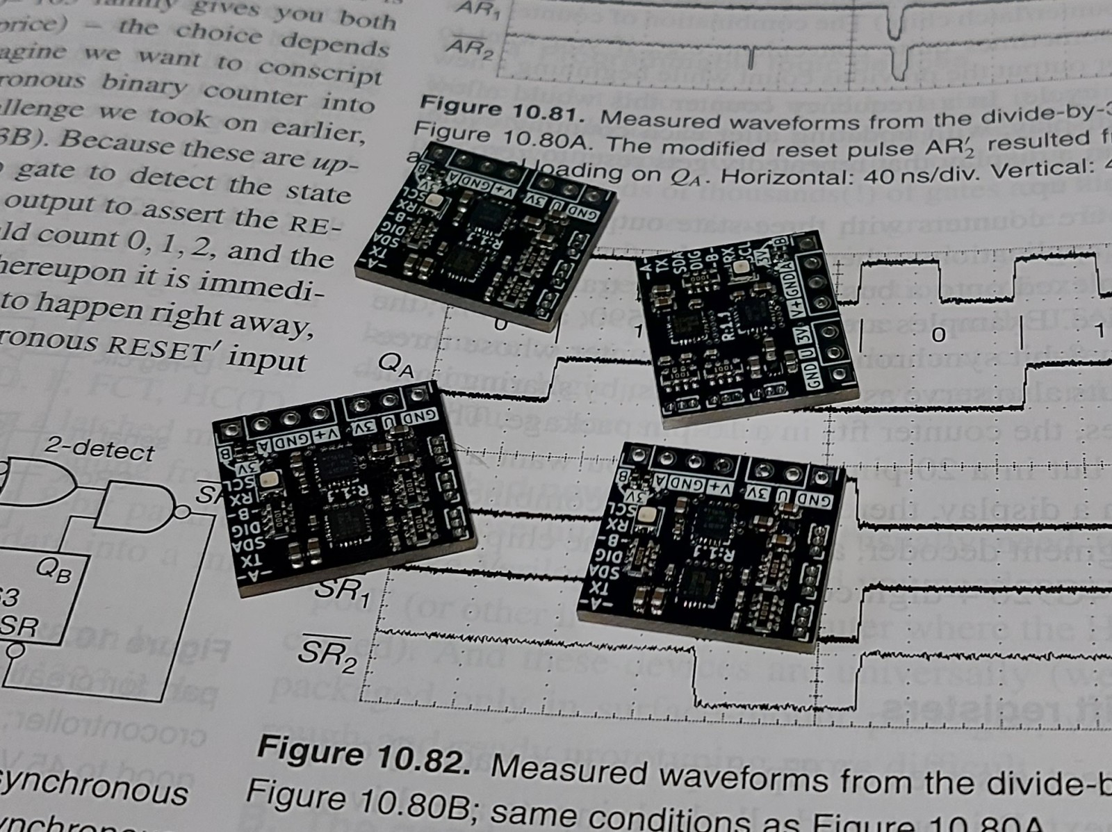
I managed to accomplish all they asked for with a couple bonuses thrown in. The resulting board was 18 by 20 mm with a depth less than 4 mm owing to the low profile parts I selected (other than the headers which intentionally extended out for ease of access) so it fit snugly in the allocated space. The contact sensor was able to update more frequently than they expected and I was able to automatically detect which communications protocol the board needed to use to communicate upstream so the basic digital, UART, and I2C protocols shared the same two pins!
Unfortunately the project is currently closed source, so I’ll be rather light on the details of this project for the time being.
Requirements
- Read strain gauges placed around print head
- Convert strain gauge readings to 3D force vector
- Alert system over a digital pin if contact force was detected
- Accept a digital signal to tare/zero the sensor
Objectives
- Allow for calibration after assembly
- Fit within a 22 by 20 by 4 mm volume
- Have an RGB LED for status indication
- Allow for I2C and UART communications
Takeaways
- Minaturization is fun but hard
- Nothing beats testing in real hardware
- Avoid having wires share holes on your board for easier assembly. I did this for the strain gauge half-bridges and it was a bit of a headache to wrangle at times to hold both wires in at once for soldering.
- Always check your microcontroller fuses!
- Strain gauges are very well matched
Detailed Report
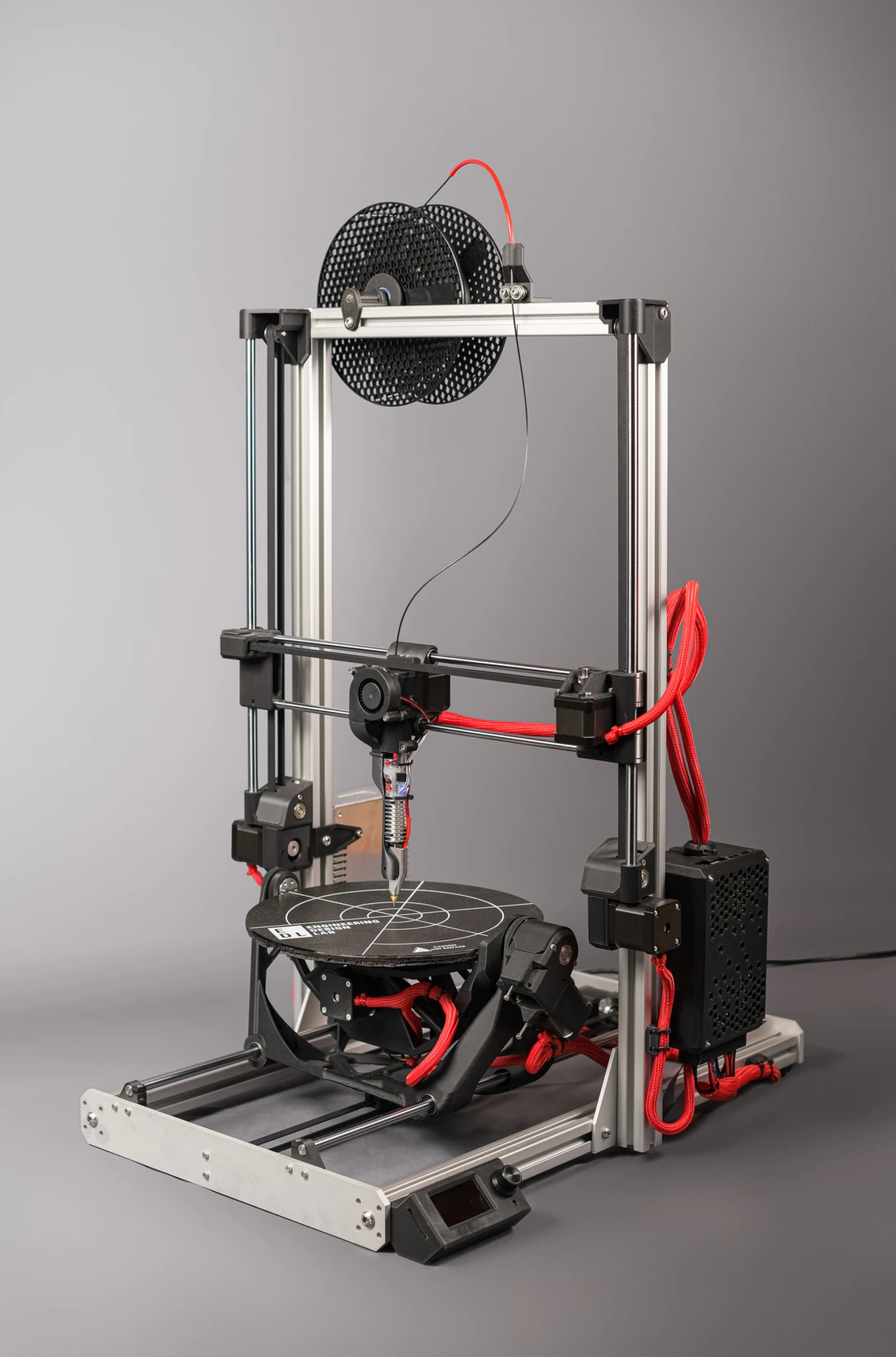
A friend of mine was working at a company (EDL (Engineering Design Lab)) designing a new 3D printer, that would become the PLU5. Unlike many other 3D printers, it would be five-axis rather than three: the print bed can rotate and tilt while the print head moves relative to the print bed in X, Y, and Z. The reasoning for this was to allow for more advanced and efficient slicing methods to print things faster and cheaper by using less support material but also potentially more performant by using a more flexible infill strategy (rather than just stacking layer by layer which is vulnerable to delamination and other undesirable effects). They explain it better on their site, please check it out!
Since there was a lot of kinematics to consider in this approach, it was vital to have the printer self-calibrate its motion. Their scheme was to use the print head as a contact sensor as it went through a controlled motion over the print bed. To this end they needed a reliable sensor to detect the faintest of contact and report it quickly, they settled on wanting to use embedded strain gauges as the method to deduce contact, turning the print head into a load cell for all intents and purposes.
My job was to design the circuit that would read these strain gauges and output the state of the print head. It ideally had to fit within a cavity they designed into the extruder, 18 by 20 mm, so that there wouldn’t be a long run length for the sensitive strain gauge signals nor a complicated wring harness to the printer’s motherboard.
As for the specifics of the communication between my board and the motherboard, I was requested to at the minimum have a way of outputting a digital signal for contact and accepting another for taring (zeroing) the reading. It was requested that I try to support more complicated digital protocols like I2C or UART for future firmware revisions as well as calibration and configuration after assembly.
Circuit Design
I unfortunately will be pretty secretive with the design for the time being. Luckily the simple scope of the system (strain gauges -> microcontroller -> contact signal) played into helping me maintain the required small footprint and low material cost per unit. I selected a microcontroller based on my familiarity and it having the ability to multiplex all the protocols I was interested on the same two pins allowing the system to use a four wire harness to the motherboard.
There were only two other ICs on board, the linear regulator to supply low-noise power, and a discrete analog to digital converter (ADC) to read the strain gauges accurately and at a high frequency. The ADC I selected was well suited to the task as it was able to run off a shared clock with the main microcontroller and had 3 differential input pairs perfect for monitoring three axes of force! Other than these the only none passive component on board was an RGB LED I added for visual feedback.
In the end the boards I designed were within the bounds to be nested inside the print head without protruding at 18 by 20 mm. I managed to put all the headers that needed to be accessed after installation (for communication and reprogramming) along one side and the headers for the strain gauges along the other
Assembly and Testing
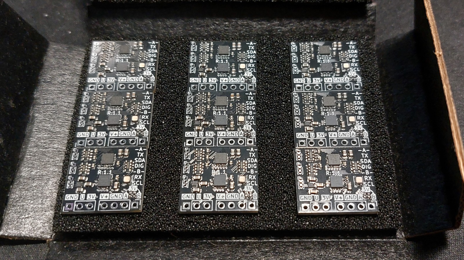
Assembling the boards was nothing too new to me, standard SMD assembly by hand. This was the first time I had assembled so many of the same board at once, since most of my projects have been one-offs or limited to only a couple as spares/replacements if needed. The client needed five functional boards since they were making five prototypes, so I ordered components for 10 boards to have some wiggle room. Boy did I need it later on.
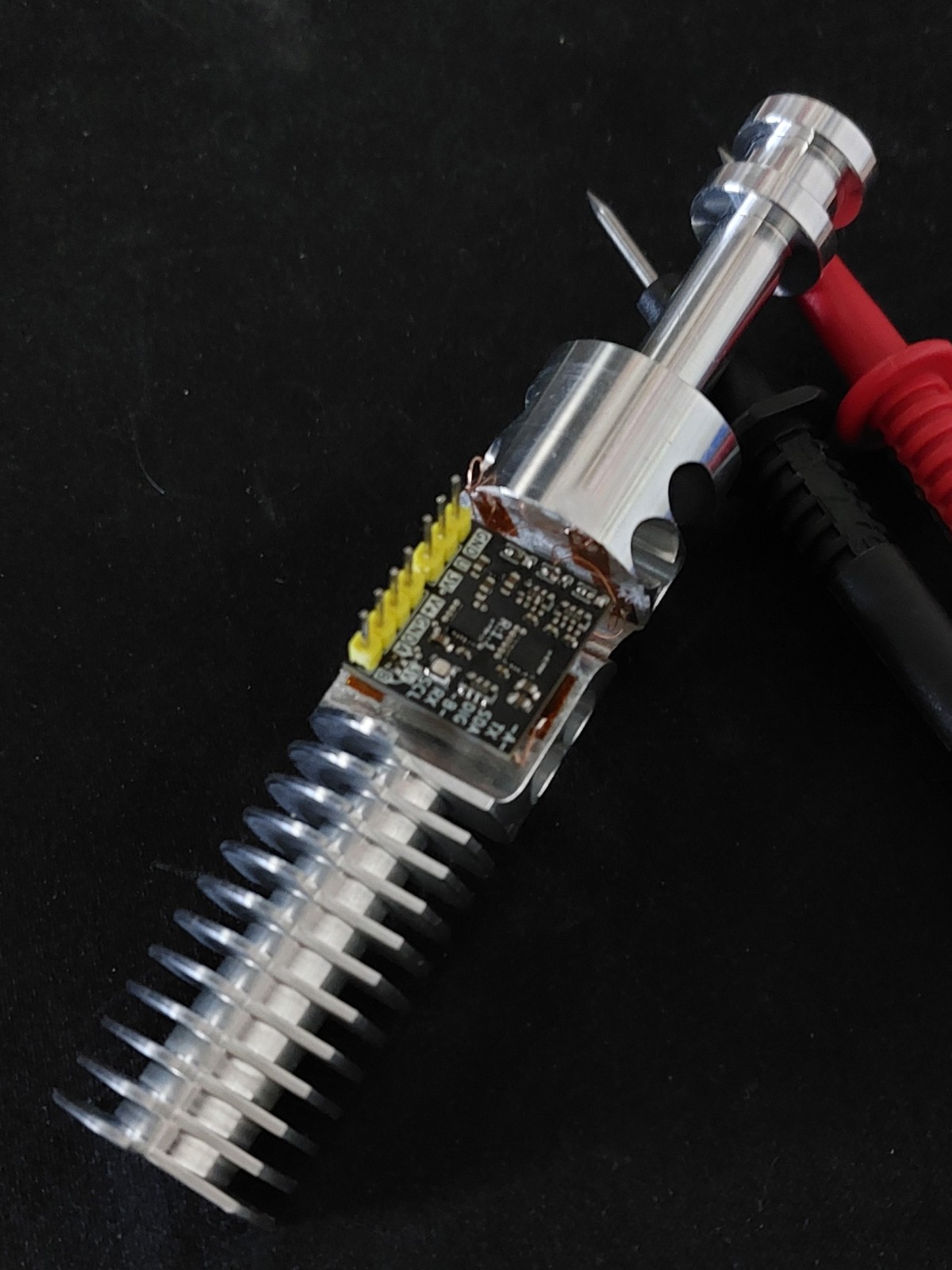
Assembling these boards into the print heads wasn’t too difficult. I only needed to solder 16 wires to each board, 12 of which were from the strain gauges, the other four being the cable harness to the motherboard.
There was only two minor things I would have changed about this assembly process is that I would get strain gauges with longer leads. They were placed prior to the board assembly so their lead lengths sometimes caused me some issues in getting comfortable working angles. Secondly, I would have remade the boards to have a single hole for each lead, in an effort to save space I decided I would feed both middle leads for a given strain gauge half bridge into the same hole, this required both wire to be inserted at the same time which was difficult for some pairs.
Programming
Programming was pretty simple for the most part. There were three main portions of the code all written in C++:
- Reading in the strain gauges (via off-chip ADC)
- Processing ADC readings into forces and deciding if there is contact or not
- Communicating with the printer’s mother board and displaying status via LED
Prior to the board arriving (they were heavily delayed,) I made use of some spare microcontrollers I had of the same model and prepared much of the code, especially the code related to monitoring the forces and communication with the motherboard. This was done using tools I had experience with from my previous work, and was easily tested using hard-coded test cases and communication modules.
The only code that I was unable to test and verify extensively in advance was the ADC-related code since I didn’t have any of those on convenient breakouts. Even so I prepared what would eventually prove to be a functional library for the ADC based off its data sheet. Once the chips arrived this needed minimal tuning.
Debugging
My first board I accidentally reversed the polarity on and fried, so most of this happened on the second.
At the start I was having some issues with my code causing the circuit to eventually freeze and become unresponsive. Having the LED on the board was super helpful for developing code since I would have it change colour as it progressed through the code and thus I could determine which portions were causing the crash. There were two main issues that caused the system to crash. I also added a “breathing” effect where LED would gradually chage brightness during normal operation so it would be apparent if the system froze.
Firstly the was some odd behaviour regarding the CS pin for the ADC from the microcontroller being interfered on by the RGB LED signals for some reason (this happened on multiple boards, no shorts detected, perhaps some bug in the microcontroller?).
The second issue came from the way I connected the “data available”, DAV, signal from the ADC to the microcontroller and the SPI library I was using for that microcontroller. In short the ADC would assert low on DAV when there was data (it would assert high otherwise), this DAV signal was coincidentally connected to the nSS pin on the microcontroller. There was a feature in the microcontroller that could be enabled so that if nSS was asserted low, that it would go into SPI slave mode automatically and wait for a transfer to complete. This is what the ADC was inadvertently doing to the microcontroller, causing it to freeze as it waited for the clock signal to arrive that never would. To remedy this I had to slightly modify the library to omit this feature so that the microcontroller wouldn’t stop anytiome there was data available.
Once I addressed those two issues the rest of the debugging was just the usual ironing out some minor logic bugs that went unnoticed in prior tests without the real hardware present.
With the code completed on my second board I went ahead and started flashing the remaining eight boards to deliver to my client. The third board worked fine but the remaining boards worked but not properly, their were sending garbage over their UART connection. However it was repeatable garbage, which after a few stressful hours of trouble shooting I realized meant that they probably had a clocking issue. I hadn’t set their configuration fuses properly, so they couldn’t do UART properly! Once I burned their fuses correctly and reuploaded the code they all worked and were ready!
I did lose two additional boards due to other isolated hardware issues during this frenzy until I realized the fuse issue, so the final functional board count was seven of ten, which was still more than the five required!
Outcomes
The project was completed in the nick of time and the client was incredibly satisfied! They were impressed with its performance on all fronts and had a fun time testing its responsiveness with their fingertip when it was all assembled.
I’ve made some revisions on the design based on issues I troubleshot and improvements for assembly I identified. I hope the project goes well for them and I can work with them to get these revised designs manufactured en mass!