3D Magnetic Field Generator
Table of Contents
Overview
When I was a research assistant for AMNL my primary job was to design and build a system to generate alternating 3D magnetic fields at frequencies in the 10’s of kHz, across a workspace on the order of a couple cm. This was to be used to later test and tune the hyperthermia therapy we were developing where these fields were meant to cause nanoparticles to generate heat.
In addition to building the field generator, I was meant to deliver a control scheme for it to aid in localizing the magnitude of the resulting magnetic field as well as a recommended particle size derived from either simulations or experiments.
In the end I was able to deliver a completely assembled design with my simulations. However I was unable to properly compare and calibrate my simulation to the result of my real world trials before my term ended. Neither was I able to conclusively derive a simulation that was able to predict the heat generated by nanoparticles, and thus the optimal particle size.
Requirements
- Use iron nanoparticles between 200nm and 5um diameter
- Generate a controlled 3D magnetic field with a strength exceeding 20mT across the work volume
- Use the lab standard coil driver
- ±50 V, 5 A output capability
- Use an analog voltage input that is magnified
- Output frequency limited to 30 kHz
- Create and verify simulation models of the following in COMSOL Multiphysics:
- The generated 3D magnetic field
- The interaction of nanoparticles with varying alternating magnetic fields
- The heat density required to reach and maintain the desired therapy temperature
- Assemble and test the magnet field generator
- Provide documented reasons for my design decisions either from literature, experiments, or simulations
Objectives
- Be able to focus the magnetic field within targeted parts of the brain
- Generate and maintain a temperature between 43 °C and 45 °C in a sample
- Apparatus should fit within the microscopes generally used by the lab
- Complete the design and assembly of the system by the middle of summer
- Use the remainder of summer to verify the design and perform tests on samples
Takeaways
- This was by far my most thoroughly researched project. Both out of necessity to understand the new topics as well as to justify my choices
- Research work often doesn’t work out as straight forward as expected
- It is important to keep yourself to deadlines and a plan, otherwise things may slide out of control
- Magnetism is an interesting phenomenon and how it interacts with matter to generate heat
- Fit tests need to be done properly with all parts in place when testing
Project Status at Handover
I did not complete the project entirely, although it wasn’t expected that we would collect all our data by the end of my term anyways. Here is a short list of what I handed over to those taking over after me:
- A completed field generator
- Partially calibrated
- Four driver boards for each pair of magnetic tweezers
- Collection of journal and research articles I used to justify my choices and used to guide my simulations
- All my simulations, even the ones partially completed:
- Magnetic field with drive currents
- Simulations for the heat generated by nanoparticles in the alternating magnetic field (partially completed)
Detailed Report
My main task to aid in the development of an alternative hyperthermia-based therapy for glioblastoma as part of of the Advanced Micro and Nanosystems Lab (AMNL) at the University of Toronto was to develop and verify the design for an apparatus that can generate an alternating, 3D magnetic field and determine how to best generate heat from ferromagnetic nanoparticles inside the field. This heat would be used to raise the temperature of the brain (focused on the tumour region) above 43 °C to begin killing the cancer cells, while not exceeding 45 °C which would result in damage for healthy cells.
In addition to the design I was asked to provide supporting simulations to justify my designs and help predict its behaviour, as well as simulations to help us predict the behaviour of nanoparticles when exposed to these fields, and how this heat would affect the tissue around them.
Research
Unlike most of my previous projects, this one required significant research. Firstly to help me get up to speed on the subject, ad secondly to aid me in my choices either as guidance or validation by seeing how things went for others attempting similar work. So research and literature review were a consistent part of this project, there wasn’t a day that passed where I didn’t look at at least one paper in the process of working.
I gathered my research not dissimilarly to when I was doing assignments in undergrad, through searches on the web or though the University’s libraries. Occasionally, especially at the beginning my supervisor would provide me with papers they found would be useful for me. I kept a couple dozen papers saved on my computer that I regularly referenced.
The topic that I spent the most time researching by far was magneto-thermal interactions of nanoparticles. This was because it was the most foreign topic to me within my scope, and also the one that is currently least understood in general of all my topics. So much so that COMSOL Multiphysics did not instill confidence in me that it would simulate it properly so I was researching the current analytical models for magnetic losses and doing calculations by hand and with computational software in parallel.
To get specific, the magneto-thermal interactions at micro-scale are quite different to those at the macro-scale. At the macro-scale frequencies in the lower 10’s of kHz range are used which are used to induce eddy currents into the material which then generate heat through resistive losses in the material. On the nano-scale however, there is simply not enough bulk in the particles to generate any usable currents and instead the primary mechanism to generate heat is through hysteresis losses and/or particle relaxation as the particle is alternatingly magnetized, which is generally done in the low 100’s of kHz.
Even with this literature investigating and codifying the relationships at each end, our work feel into a middle ground that I couldn’t find much similar work to compare our efforts to. Most nanoparticle heating research was done with particles between 10 nm and 20 nm in diameter, compared to ours that started at 200 nm. They used frequencies generally between 120 kHz and 250 kHz, while due to the equipment we had we were limited to about 30 kHz. Being these orders of magnitudes off made me very cautious with the results of any simulation and I stepped carefully though any calculation I performed myself.
Making the Magnet Apparatus
The magnetic field generator took two iterations to design. This is due to me failing to improperly fit-testing my first iteration due not having all its components printed in the right quantities, with one part missing entirely. As a result of this it took longer than expected and meant I was unable to properly complete my work calibrating and testing the system because I had only finished assembling the second revision as my term was ending.
Initial design
Once I had completed my initial reading and research, I began designing the 3D magnetic field generator apparatus with some directions and suggestions from my supervisor.
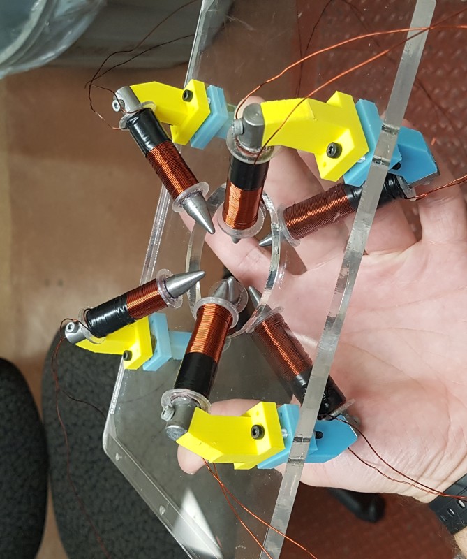
The main direction given for the final design, other than informing me that I would need to fit the microscopes, was that they wanted a system of eight magnetic tweezers arranged in pairs. This would form four axes of control intersecting the centre of the workspace since each set of coils forming an axis would be wired together and thus be generating equal but opposite magnetic fields.
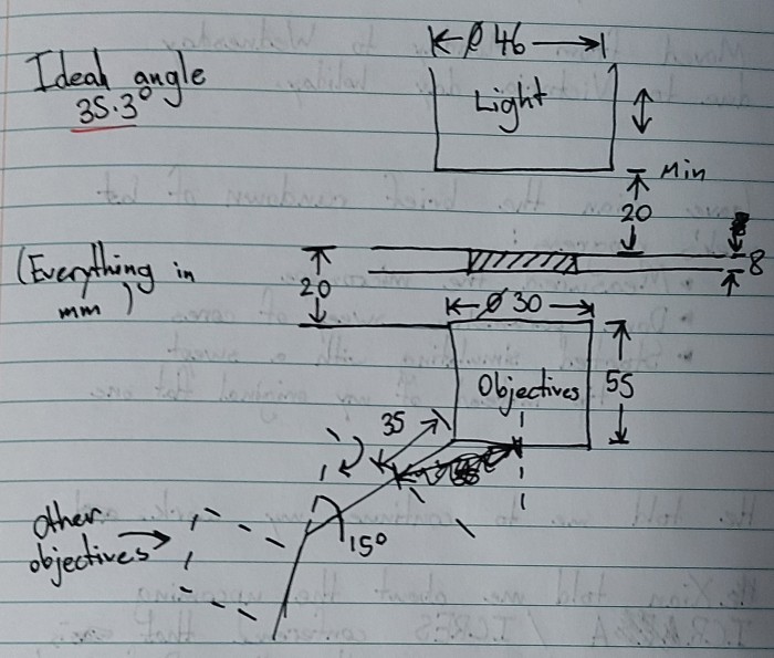
Measurements
The design needed to fit within the Nikon microscopes used by the lab and allow for a minimally obstructed view of the work volume when mounted, so I went into the lab to measure the key dimensions of the microscope for me such as the mounting for the interchangeable microscope platforms and the position of the optics relative to the platform. I had to consider a larger volume when designing the apparatus because this was the first time they were trying to have such a large 3D workspace, much of their previous research was planar or had small z-dimensions so the regions above and below the platform were rarely extended into.
In addition to measuring the physical dimensions of the microscope I also had to determine the frequency response of the standard coil driver used in the AMNL, since I was going to be using it for this project. These were designed to drive coils with a slowly changing, basically steady current, not the rapidly oscillating current as we were intending to use them for. So I performed a frequency sweep starting at 1 kHz and raising it until the output was useless, either due to attenuation or other wave alteration.
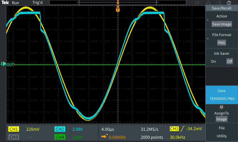
My findings from this sweep were that our driver boards were producing acceptable outputs up to about 30 kHz. Above that and attenuation, clipping, and other effects make the waves unusable. This didn’t surprise us given that the output stage of the design was using high-end audio-grade transistors for amplification, so performance above 20 kHz for them is not necessary.
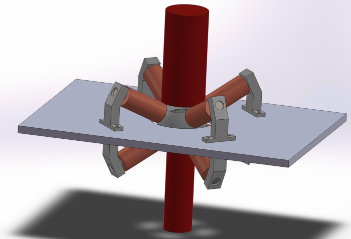
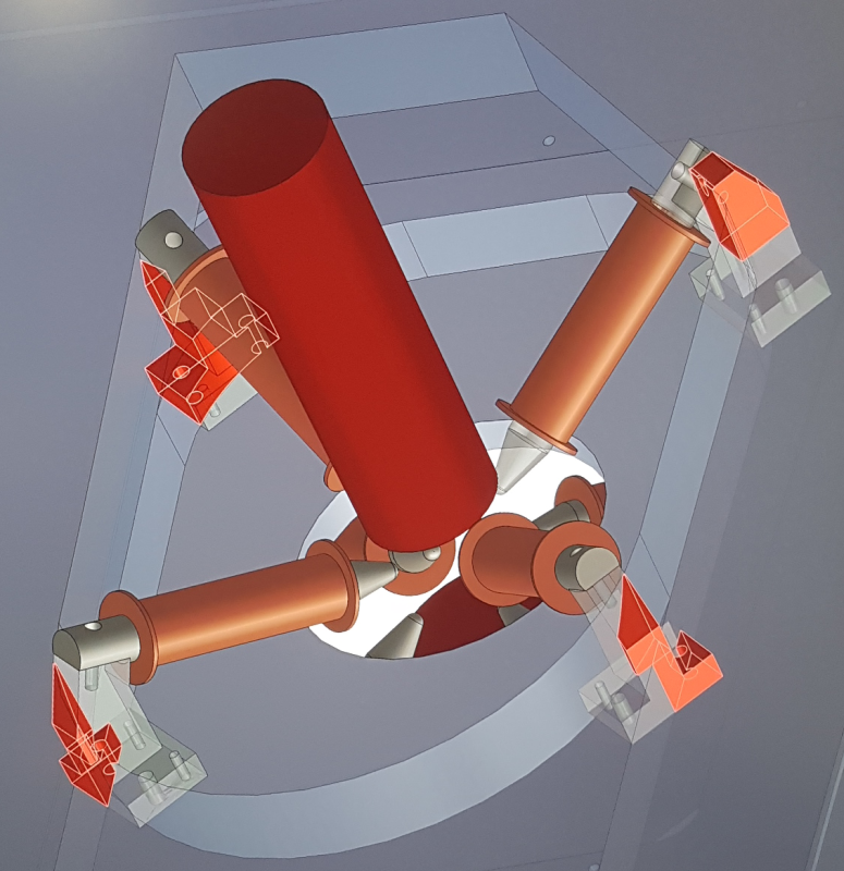
Mechanical Design and CAD
The system was actually pretty simple mechanically, as it had no moving parts. The difficulty of the design came from the requirement for it to both be a well aligned design and to not intersect the microscope. All the design work was done in SolidWorks.
To start the design I prepared a sketch of the optics with the platform centred underneath it to mark out where I could not intersect, added a circle for the workspace, and then I tried to fit in my coils as best I could around these obstacles. I tried to keep the axis of the coils as close to 35.3° relative to the platform, by having each tweezer tip at this angle on the edge of the workspace would form a virtual cube inside the sphere and the magnetic fields would be most evenly distributed through the work space.
I then focused on alternating between simulations and CAD to iteratively design and place the coils and their cores, until a satisfactory design was met. In the end the design had the coils not at the 35.3°, but closer to 30° from the platform as this allowed for enough strength through the workspace without interfering with the microscope.
Once the details related to the coils were set, I created supports and had an initial assembly.
Magnetic Design Simulations
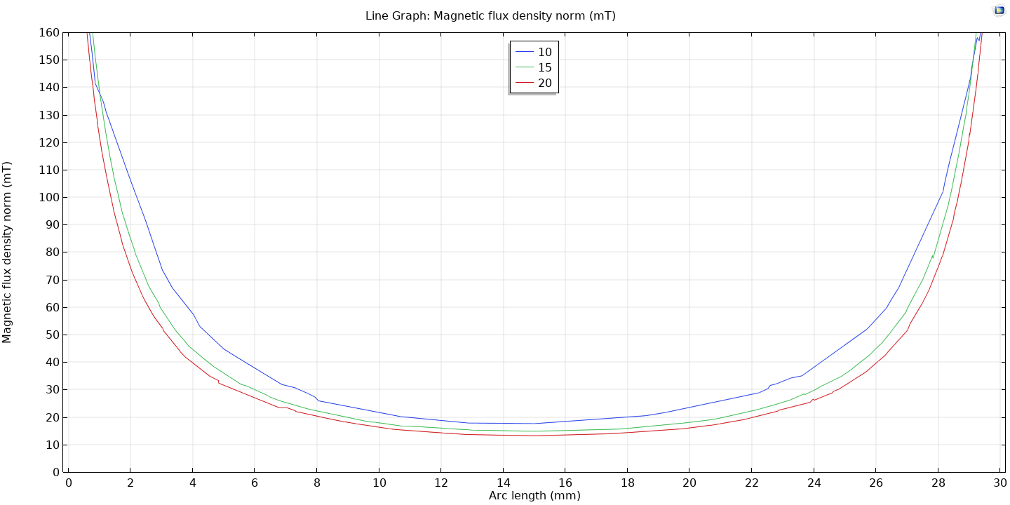
Simulations were done in parallel with the CAD of the apparatus to see how changes in the design would affect the expected field it would produce. All simulations done for the design of the apparatus were done in COMSOL.
My simulations were generally set up to focus on all of the coils operating at maximum current (5 A), this would reveal the expected maximum field strength attainable should the system be built. These tests would start as single configuration (I guess “standard” simulations) until I was confident in my results, at which point I began to use parametric sweeps in COMSOL to quickly iterate through various configurations and then compare the results across them afterwards easily. Below is an example of the results I could see from a parametric sweep where I changed the distance the coils were from the boundary of the workspace. Each line represents the strength of magnetic field from one end of the workspace to the other.
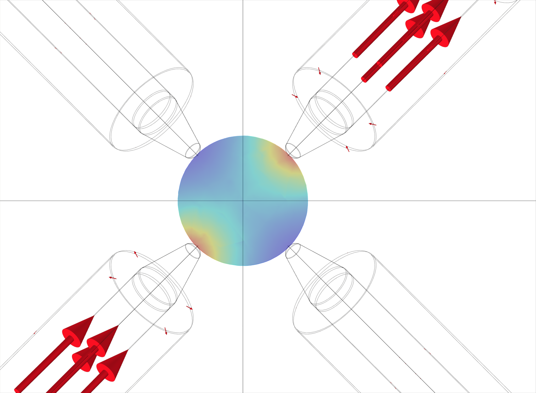
Once I had settled on a design of interest I would look to quantify the individual contributions of a single pair of coils to the overall field. This would allow me to see if that setup had regions that were clearly controlled by only one set of coils and thus “localized” (this was preferred) or if each pair’s contributions were almost indistinguishable in the whole. In the figure below, one can see that this configuration has rather localized contributions to the field in the workspace. The highest strength is clearly in the quadrants closest to the tweezers, while they barely contribute past the boundaries of their respective quadrants.
Design for X
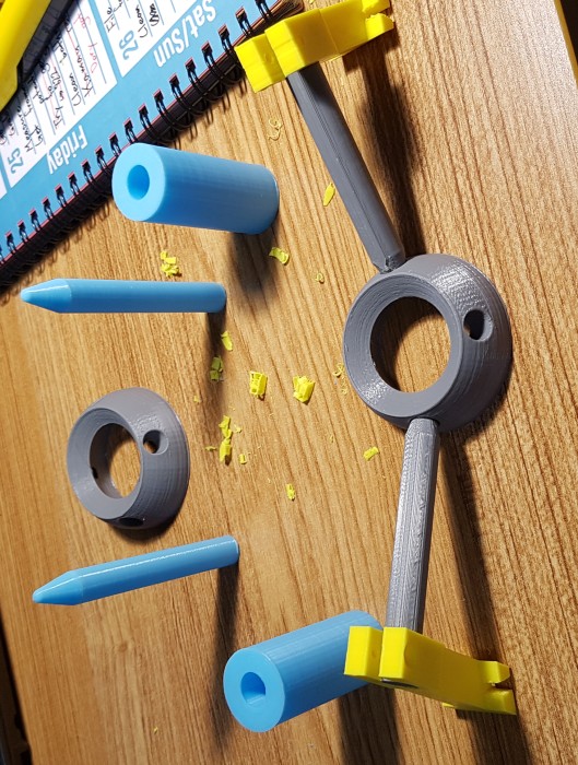
Before committing to the final design I asked my supervisor to tell me how the apparatus was going to be made so I could prepare the design accordingly. I was told that the design was going to be sent to a machine shop the lab had previously worked with in China, where it would be CNC milled out of aluminum (except for the magnet cores that would be made of iron). The windings would be done my hand in the lab, most likely by me.
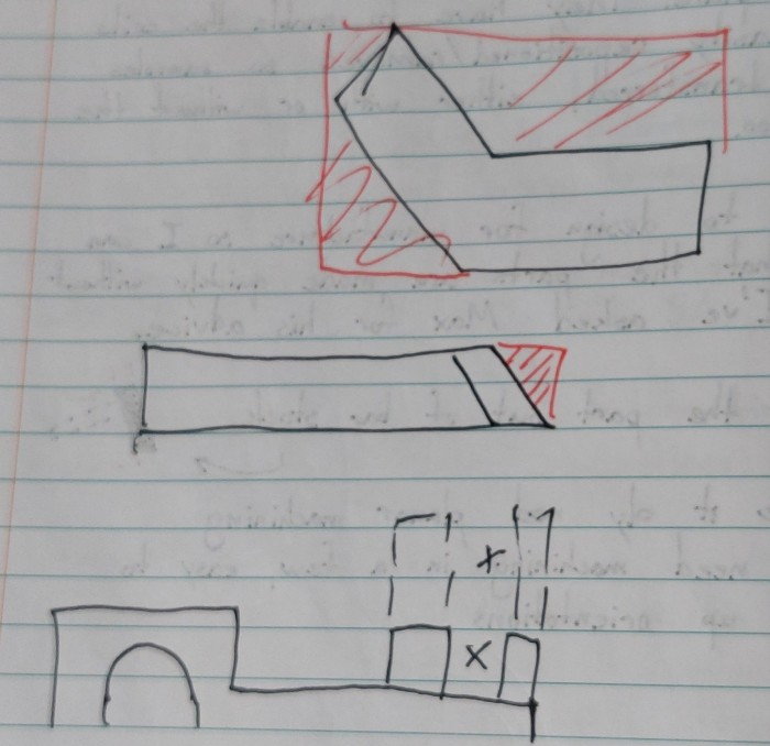
With this in mind I redesigned my tweezer holders to be more efficiently machined from bar stock by wasting less material (shown in red). A small exercise in “Design for Manufacture”.
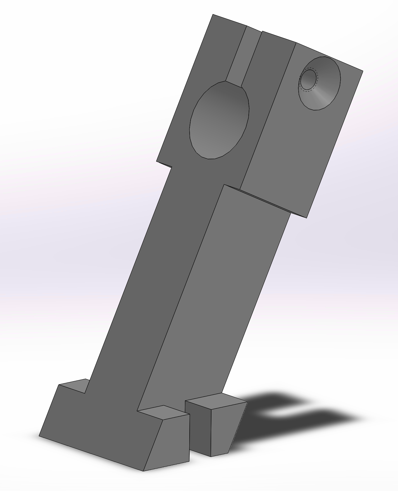
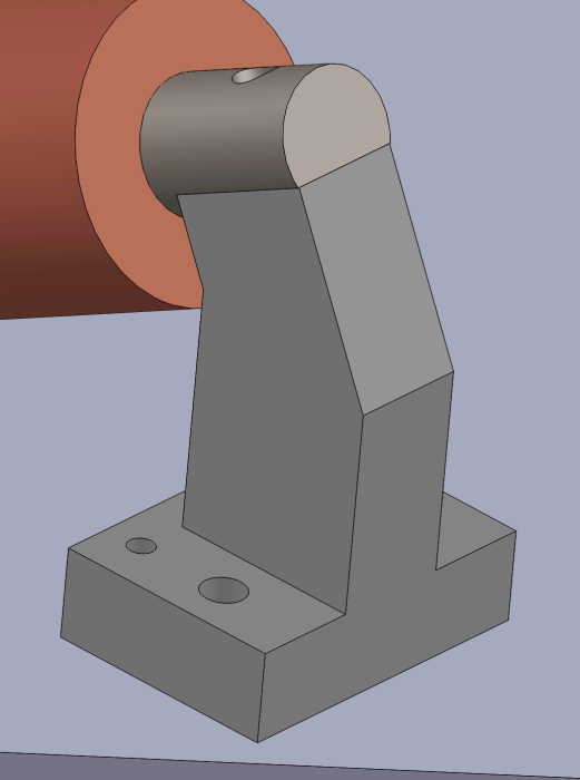
This design was eventually returned closer to the original design, and the core slightly modified with a flat where is meets the holder. The goal of this revision was to allow for easier adjustments where precision in assembly or machining could not be guaranteed, by loosening and then tightening down on the end of the core directly.
Fit Test
I preformed a fit test of the model in the microscope using 3D-printed parts. Unfortunately I didn’t get a test replica of the platform plate I designed as it was far too large to print with what printers we had available to us. I felt this was acceptable because the platform wouldn’t occupy any more space than the one I had measured, just that it would have the proper holes to mount the holders. When I assembled them on the microscope, these parts appeared to fit without an issue intersecting either the optics or main frame.
Actually Building it
I finished my final version of my initial design around the end of July. This was about a month or so later than we initially expected, however it wasn’t entirely unjustified nor deal-breaking for our schedule.
The Structure
The physical structure of the apparatus I designed (platform, holders, cores) were all going to be made by the machine shop in China our group had worked with before. However, before they could produce the parts there was an outbreak of COVID-19 in their province of China so all businesses were required to stop for three weeks. As a result of this we changed course and paid for the work to be done in the University’s machine shop instead. They laser cut the platform and machine the cores for the coils, we 3D-printed the holders on our own. This was completed approximately three weeks before the Chinese parts finally arrived!
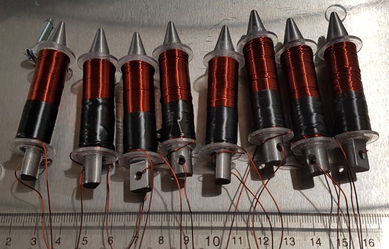
Although the lab had a device that could wind cores automatically for us, my cores were too small and lacked the geometry to work with it, so I had to hand-wind all the coils. Originally I was supposed to use 18 AWG wire, however it proved to be very difficult to work with by hand given it’s stiffness so we moved down to 24 AWG. This brought the benefit of it not only being easier to wind, but also allowing more windings in the same volume thanks to its smaller cross-section. This meant that if we were able to pass an equivalent current through these coils, the field generated would be stronger.
The original coils were meant to have about 150 turns each. With 24 AWG wire I was able to wind roughly 300 turns on each!
Once the coils were wound and ready, the rest of the assembly was a simple job of fastening 16 bolts down. Other than the leads dangling from the coils annoying me during this as I was constantly flipping the assembly to put the bolts in to secure the holders, not much to say.
The Coil Drivers
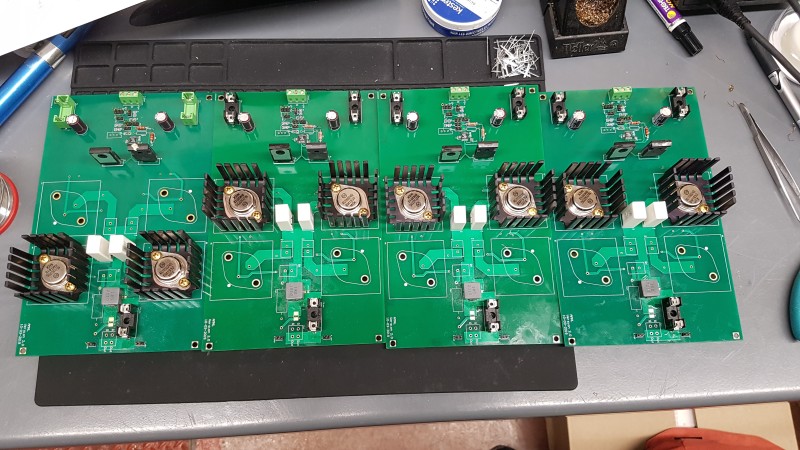
There isn’t too much interesting to say about the coil driver design assembly on my behalf. I was provided the schematics, parts, and boards, and I assembled them as instructed on the schematic using the primarily through-hole components. I made the four identical boards for my project, no issues with any of them during assembly or in functionality testing afterwards.
Actually Testing it
Since I assembled the circuit boards first as I wanted for the other parts to be made, I tested them with a dummy generic coil. As mentioned before, they all passed without issues.
The same could not be said of the magnet generator. Although all the parts fit together perfectly on it, once I tried to install it on the microscope two things became immediately evident:
- I had somehow messed up the length of the platform plate. (I traced this back to a note that I accidentally wrote 255 mm instead of 235 mm)
- There was unforeseen interference with the bottom side and the frame. This was somehow missed with the fit check.
I took measurement of the entire frame of the microscope, not just the optics so I could see how much work needed to be redone or if there was some hacky way around it. Boy did I have my work cut out for me.
Revision to Fit Properly
All this interference was caused by the holders, so they needed to be changed - ideally without needing any other modifications. To pull them into the centre of the platform I changed them from having the core bolt to them, to having the holder come in two parts: one to anchor to the platform and hold the coil, the other to come down atop the coil and clamp down and locking the coil in place. These could be readily 3D-printed and used, the only additional modification was going to be the addition of some new holes to the platform I had made to anchor the new holders to closer to the centre, which could be easily done with a hand drill.
This modification also had the side-effect of increasing the expected viewing area by 50% from what I was originally striving for.
I had the parts printed, however I ran out of time before I could drill the new holes. I also unfortunately forgot to take any photos of these last minute revisions so I have nothing to show you for these.
Making the Control System
Even with a non-fitting apparatus, I could start to work on calibrating the magnetic field model to reality, and thus provide a model to predict the magnetic field generated given a set of control currents/voltages. This model could then be inverted to determine the approximate control currents/voltages needed for magnetically targeting a specific region of the workspace.
My work to do this was pretty simple, I would operate the system under a known and stable condition and then record the magnetic field strength throughout the work volume.
To measure at a set of known points in the 3D workspace I resorted to imposing a grid of regularly spaced points on a drawing of the apparatus (normal to the plane I was trying to calibrate on). I then would print these out at 100% scale, cut them, and then tape them into place in the apparatus. For my calibrations, I used a 5 mm grid spacing for points on a plane.
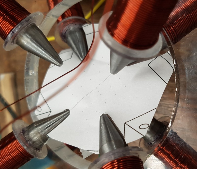
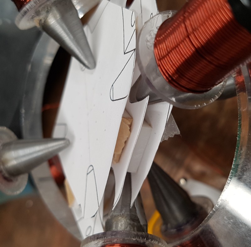
Using a Gaussmeter, I would probe the field at each point and record it. To calibrate in the Z-direction too I would use measured pieces of foam (3 mm) sandwiched between these printed out sheets, align the grids as best I could, and repeat the process.
These measurements were then meant to be compared to simulation from COMSOL and be used to make a realistic model. Unfortunately given the delays to produce the generator I was unable to finish this before my term was over.
Making Magneto-Thermal Simulations
This was the new frontier for me, and honestly most of the team too. Generally much of AMNL’s previous work had been focused on using the magnetic fields to achieve some kinetic effect using micro- and nanoparticles, such as controlled displacements or stirring. I began work on this as I neared the end of my initial design of the magnet apparatus, roughly mid-July.
Understanding the Mechanics
I began by looking into what the mechanisms for heat generation using magnetism was at the nanoscale. To continue where I left off at in the “Research” section, there are two main phenomenon that are responsible for generating heat at this scale:
- Magnetic hysteresis losses. The energy lost as the magnetic polarity polarity of a material is changed in an alternating field.
- Relaxation, either Brownian or Néel depending on the material type. The release of heat as the material loses its magnetic polarity in the absence of a forcing field.
These can both be imagined to be the result of atomic-scale friction between the sub-atomic particles as they align themselves with respect to the magnetic field. They are both governed by a series of differential equations due to their links with time, and specific material properties. I will explain them in greater detail as I discuss the simulations I ran.
Starting Some Simulations
I started by looking at the available guides and examples for what COMSOL had to offer for magneto-thermal simulations, however it was largely at the macro-scale so very little was relevant to me. The software however did have provisions for determining the magnetic losses, and then using them as a heat source.
So began by simply playing around with the values of the simulation to see if I could approximate the results of other published trials. To do this I simply simulated a single spherical nanoparticle surrounded in water, with an alternating ambient magnetic field. This quickly resulted in issues for me because COMSOL had issues meshing the nanoparticles if they were smaller than 200 nm in diameter (most research was between 10 nm and 20 nm). However after some tweaking of material values I was able to approximate the power densities of the research at their frequencies. This success was tainted with some serious questions though:
- Congratulations, you made the results of this test (an order of magnitude larger) mimic that of a smaller particle. How can you be sure you have it set up properly for this scale once you get the right material properties?
- How will I know I have the right material properties?
- How much would my results change if I considered the other particles nearby?
- Does “Magnetic Losses” also consider relaxations of nanoparticles in a field, or does it just use hysteresis?
- Are relaxations negligible if the field is constantly present during therapy?
Determining Material Propeties
I decided to start by working on the first two questions since I believed they would be the foundation needed to address the other questions properly.
In the magnetic losses simulation of COMSOL, a differential formula is used to determine the magnetic hysteresis loop of a given material and thus the magnetic losses. This formula needs two parameters to characterize a material, \(μ’\) and \(μ’’\), these are the relative magnetic permeabilities of a material. They would be used in the formula below.
$$ B = μ_0 * (μ' - iμ'') * H $$\(B\), ambient magnetic field
\(μ_0\), permeability of vacuum
\(H\), the magnetization of the material
When ploted on a graph of \(B\) vs. \(H\) it would result in an ellipse centred on the origin. The magnetic losses per cycle can be found by taking the integral of the ellipse’s enclosed area.
These parameters are highly dependant on the application of a material and thus rarely stated in data sheets. So I began researching to determine them for myself, either through other people’s research or additional simulations. After some digging through COMSOL’s documentation, I found an application note describing how to use other simulations to gather the data one would need and then the operations needed to convert this data into the two parameters to use.
Running Out of Time
Unfortunately, I did not have the time I needed to attempt the process of determining permeabilities analytically before my placement was over. This meant that I was unable to continue and try answering my other questions so we could confidently use the simulations to predict which nanoparticles and frequency pairing would be optimal for our therapy.
As part of my hand-over I left a series of instructions for the next person to follow along and hopefully complete these simulations.