Demo Show Seat
Table of Contents
Overview
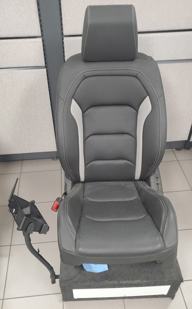
IGB Automotive had a show seat they used when exhibiting their company’s products, and they regularly change the seat and products exhibited. As they change the seat, they keep the same control electronics. With each seat they need to adjust the set points for their main product, their seat and bolster heaters accordingly. These are set based on the resistance between certain pins on the control module, which are generally set using set valued resistors.
So for each new seat a new set of resistors needed to be soldered in, and if a potential client wanted to try a variety of set points, we needed to use a selector switch with an array of resistors. To make our work in the future simpler I was tasked with implementing a digital potentiometer we could simply control with software.
This was my first embedded electronics project! It inspired me to investigate the field after I finished it.
Requirements
- Embed a digital potentiometer in place of set resistors
- Prepare LabVIEW code to control the digital potentiometer
- System must work within the automotive voltage range (7V - 14V)
Takeaways
- Embedded electronics are fun!
- Mixed voltages can lead to some interesting design choices (read: hacks)
- LabVIEW is an excellent way to create and modify virtual control interfaces
- “I wonder how I could have done this better?”
Detailed Report
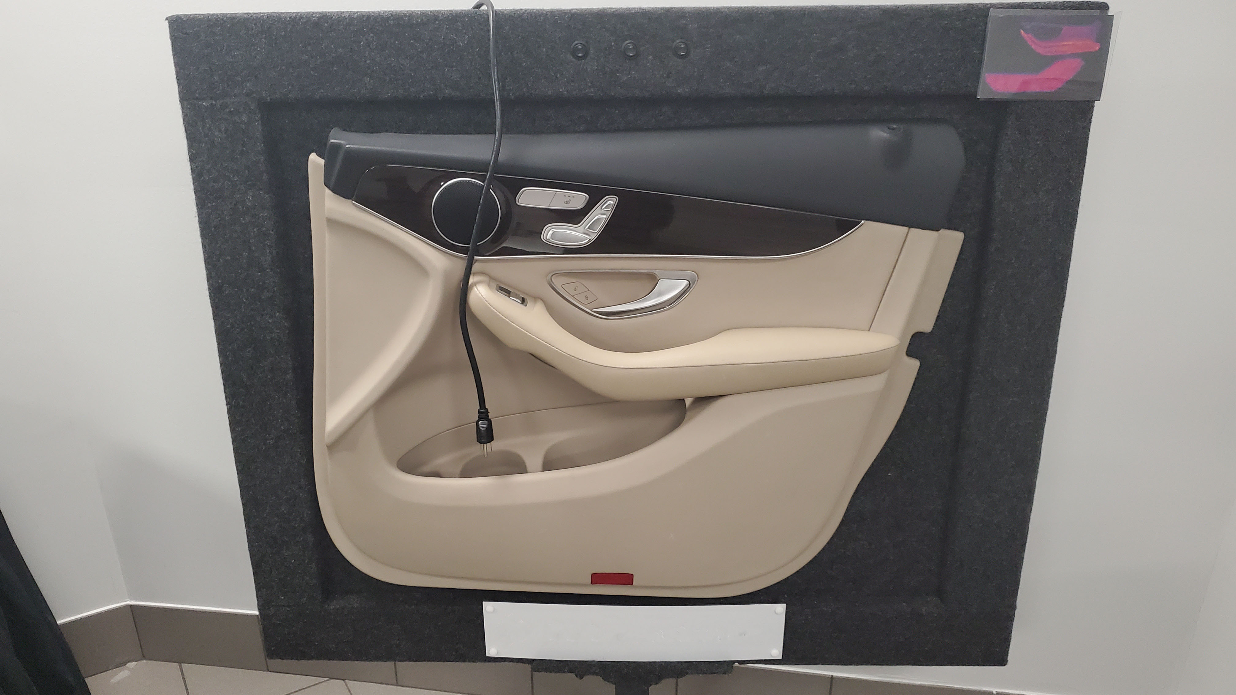
When going to industry conferences and showcases, IGB Automotive had a dedicated show seat that they would use to demonstrate their products: heating for seats, steering wheels, bolsters, as well as seat cooling. However the set points for their main products: heaters, are set using resistors external to the control module so the same module can be dropped into different vehicles without issue. However for this application it makes is much more difficult to change the set points with each new seat or set of products used since the resistors built into the control system of the seat would need changing. This also makes it difficult to demonstrate multiple set points for potential clients since a whole array of resistors would need to be used in junction with a switch.
The solution my manager tasked me to implement was replacing these resistors in the show seat with a digital potentiometer we could then adjust in software, thereby controlling the set points programmatically. Shame it didn’t turn out to be as simple as I expected but it was certainly a valuable and interesting introduction to the world of embedded electronics.
The Control System
The seat control had a couple of layers to it. Users would interact with a small all-in-one computer screen that ran a digital control interface for the features in the seat. This interface was made in LabVIEW and would communicate over USB to a Data Acquisition (DAQ) unit, which would then toggle relays that stand in for the actual switches that would be used in a vehicle. These relays would detemine the behavior of the control module (e.g. turning on the heating) which would then use the resistors for the set points (i.e. see how much heat to apply).
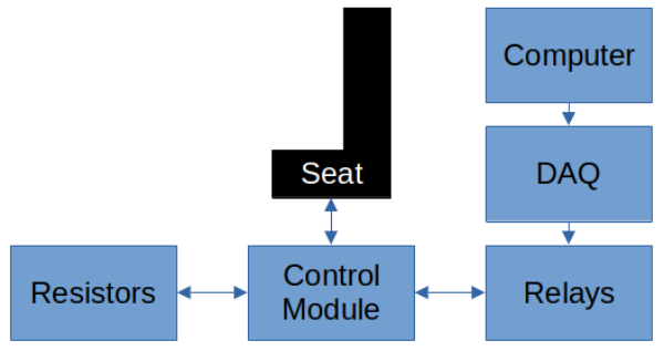
The plan is put digital potentiometers in the place of the resistors and have them controlled by the DAQs, like with the relays.
Mixed Voltages
There was one major issue, mixed voltages. Automotive standards need components to operate within 7V to 16V, nominal voltage being between 12V and 14V (our powersupply in the seat operated at about 13.5V, if I recall correctly). However most logic chips aren’t rated to operate significantly beyond 5V.
I can’t lower the entire system’s supply voltage to 5V because the control module will enter under-voltage protection as long as it is below 8V and be entirely unresponsive until the voltage rises enough (in addition to having poor heater performance). However, the digital potentiometer will be fried if exposed to the 13.5V typical of the seat system. The solution I found out through some research, as well as a sprinkle of trial and error (remember when chips were cheap?) was to push the systems to operate as close as they could to one another, just where their absolute limits overlapped slightly.
On the control module side this could also be done without sacrificing the heater performance because the control module had a seperate supply line for the heaters and the internal logic (both were still monitored for under-voltage conditions individually though). So I had the power input connected to the usual 13.5V, however the logic supply was connected to a 9V regulator.
As for the digital potentiometer there were two device ratings that combined, gauranteed the system could work. First, it could tolerate a maximum supply voltage of 7V according to the data sheet. This wasn’t enough to ensure the control module wouldn’t damage the potentiometer, which is where the second specification comes in. The potentiometer could handle voltages on its “potentiometer” pins that were up to 3V higher than the supplied voltage to the chip. This meant it could handle up to 10V on the inputs connect to the control module - the control module that was operating at 9V.
After doing this math and burning two potentiometers due to improperly configured voltage regulators (everyone starts somewhere), I had a stable system that I soldered on a protoboard for long term reliability.
Final Touches
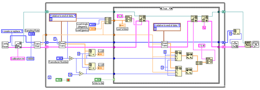
With the system soldered, I moved to reworking the code for the existing system in LabVIEW to include the ability to control the digital potentiometers. The code I had written until then was pretty basic to just test the potentiometers so seeing the full program was really neat, especially given the pictographic nature of LabVIEW code where it looked like a fascinating tapestry. It was definitely easier for me to figure out where to insert my code in this than had I been handed a similar scaled program in a more conventional language like C/C++.
Once I squeezed my code into the overall program and added a panel for the user to set the set points, the system was good to go on the road to the next show!
Lasting Impact
As I finished the project, I began to ask myself, how much faster could I have controlled the digital potentiometers had I been writing code that would have been executed directly on the DAQ rather than puppeting the DAQ over USB from the computer. It was this question that led me to start looking more into the world of microcontrollers in my own time.