Hot Wire Foam Cutter
Table of Contents
Overview
For our aircraft project, HPVDT was looking to build a hot-wire cutter for foam to use in the development process of our airfoils to make prototypes, and then the mid scale production of them when a design is set. In CNC terms I was in was in charge of sorting out the process of taking the completed G-code from our designers for the profiles and running it on some custom hardware.
Although there was another team member that was in charge of this project overall, I aided with regards to the low-level electronics needed. My contributions to this project was to aid in the design and assembly of the electronics system, as well as deploying and modifying firmware on the Arduino controlled CNC to work with the control software on the PC.
Requirements
- Control four stepper motors
- Receive instructions in the form of G-code from a PC over USB
- Have limit switches for each axis
Objectives
- Minimize cost
- Use a common hobbyist development board for control rather than something more CNC specific
Takeaways
As usual the open source community has lots of projects one can use to springboard their own. Once I found a suitable base of Grbl for the Arduino Mega with at least four axes I didn’t need to do much coding. It was really just calibrating and recording configuration specifics.
Although there would have been some undeniable satisfaction in getting to reinvent the wheel by making our own motor driver boards, purchasing commercial ones was definitely more efficient for us by almost every measure, especially development time which was important.
Detailed Report
As part of our aircraft project, HPVDT was looking to get a hot-wire cutter for foam to use in the development process of our airfoils for prototypes, and then the mid scale production of them when a design is set. Most commercial offerings were unsuitable for the team so it was decided to make our own from scratch.
A hot wire foam cutter is a basic machine in principle. There are two opposing vertical planar CNCs, between them a piece of wire is connected and held in tension through which a current flows and heats it up. A piece of foam is placed between them which is then cut according to the profiles drawn on each of the CNCs. We were heavily inspired by the work of others like How To Mechatronics.
In terms of electronics hardware, there is not a whole lot going on. There is a central controller which sends commands to the motor driver for each axis as needed. There is no positional feedback for each axis other than the limit switches, since the foam does not present any meaningful resistance to the cutting motions.
Getting the Foil Designs and G-Code
The first step in the process of making the wings was designing them. I believe the cross sections were initially designed and validated using XFOIL to then be turned into 3D wings using SolidWorks which sponsors the team with student licenses
With the foils designed we had to turn them into G-Code to command the machine to move. For this the team evaluated a couple options before settling on DevFoam for our purposes which has served us well over the course of the project.
Hardware design
The hardware design was pretty basic, owing to us selecting to use commercial modules for driving the motors. These were controlled using three signals. One to enable the motor driver, one to set the direction, and the last to move the motor one step in that direction. This meant that I only needed to make the controller that would receive G-code from the computer and generate these pulses, as well as monitor the limit switches.
After doing some looking around I found the grbl 4 axis project for Arduino Megas by dguerizec. It fit the description for exactly what we wanted the firmware to do, recieve G-code and control four independent motor axes. It was designed to run off an Arduino Mega which was also a bonus since we had a few of these laying around that we had yet to use.
The only hardware I “needed” to design was a breakout board to make it easier for us to connect everything to the Mega without making a mistake. After digging through the firmware source and reading the documentation I deduced the pins it used and made the following schematic.

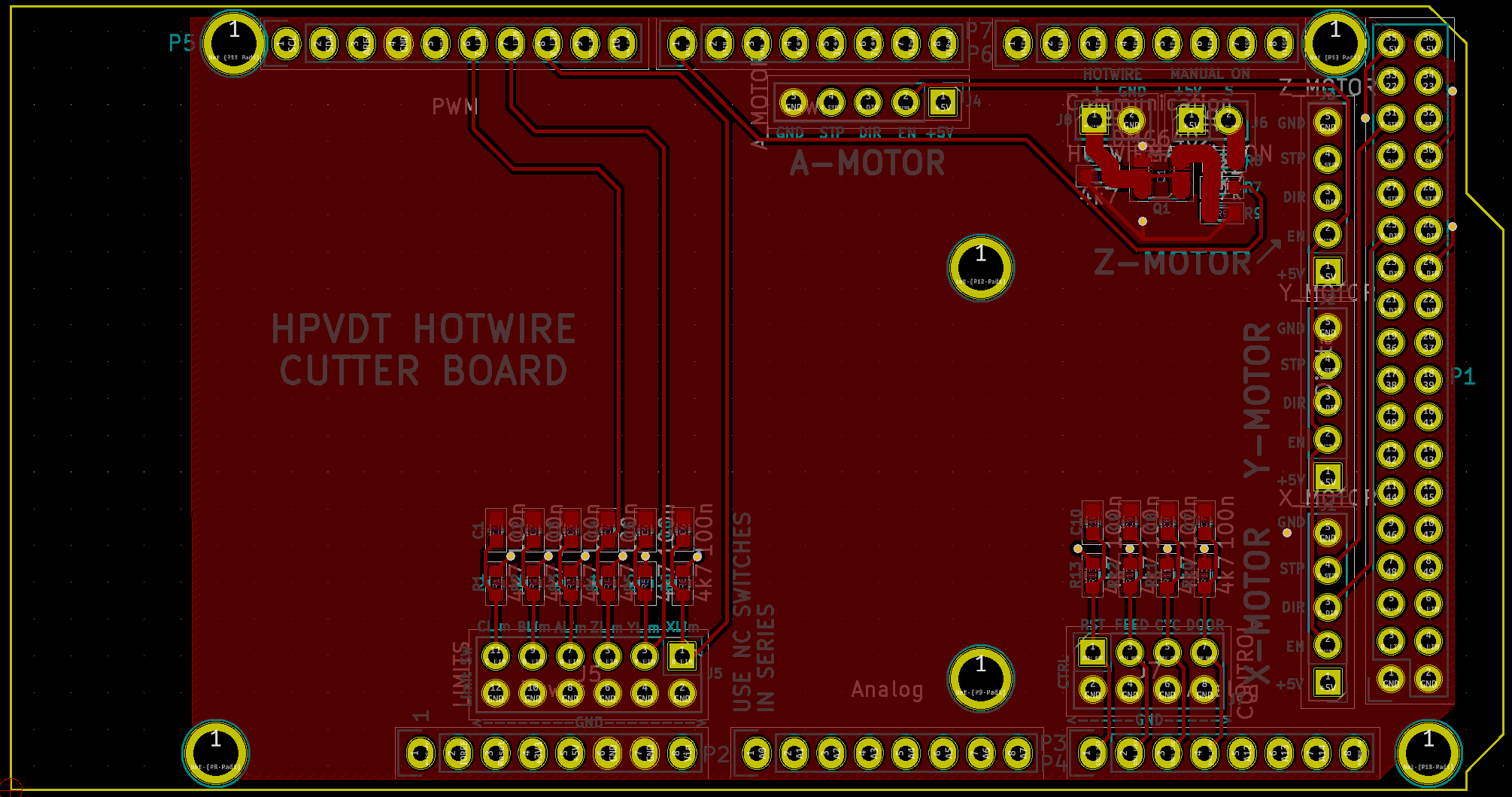
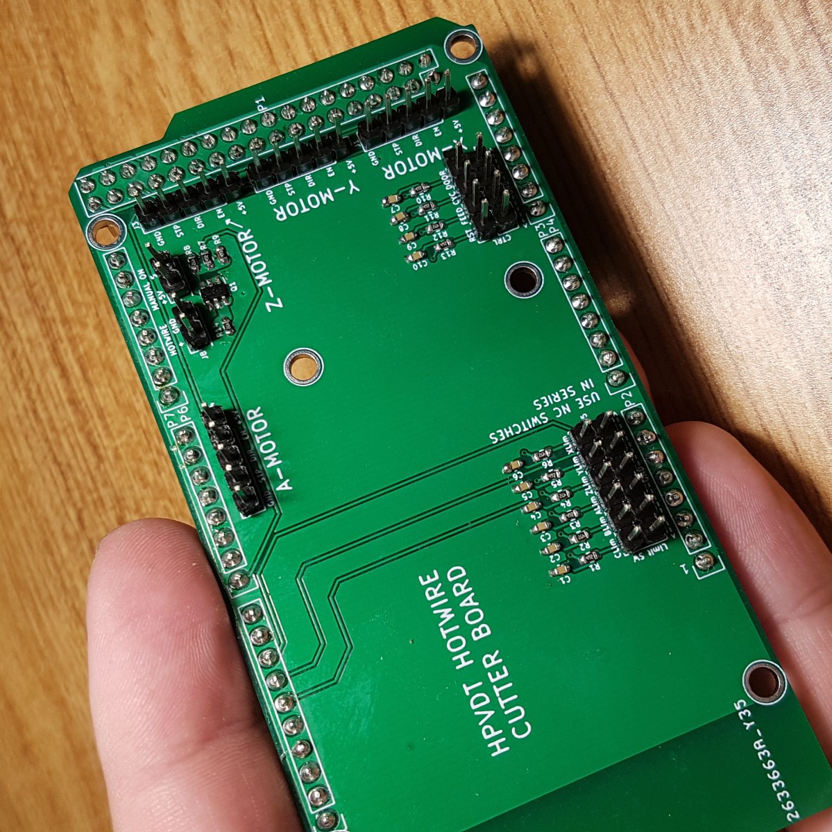
Layout
The layout of the board was made to fit as a “shield” for an Arduino Mega. I did not lay the board out, I had a new team member do this and I provided them with feedback and final approval.
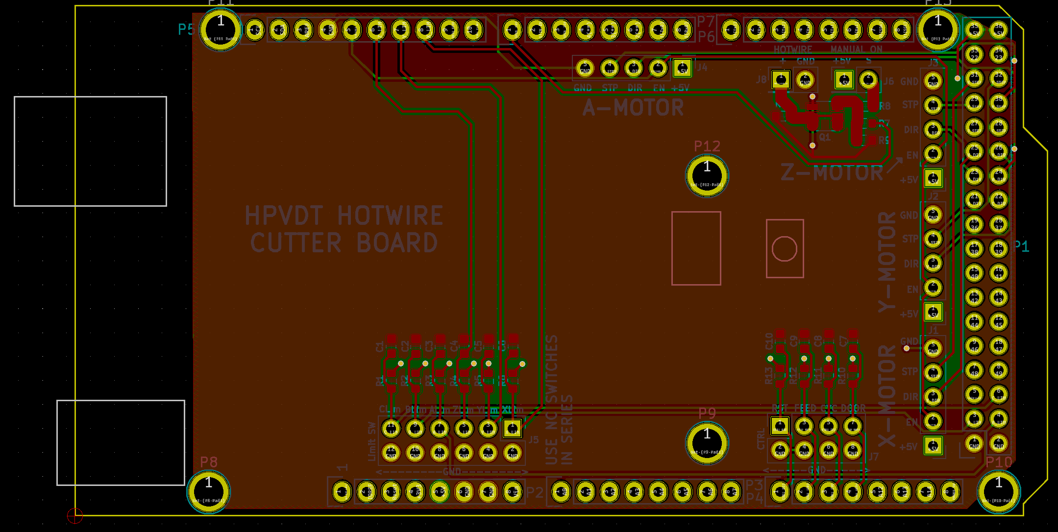
The top side of the board is where all the connection/breakouts to the CNC hardware are present. The filtering components for the different inputs (axis limits and safeties) are mounted here. Emphasis was put on clearly labelling each connection so that anyone could assemble the system without needing a schematic or intimate knowledge of the design.
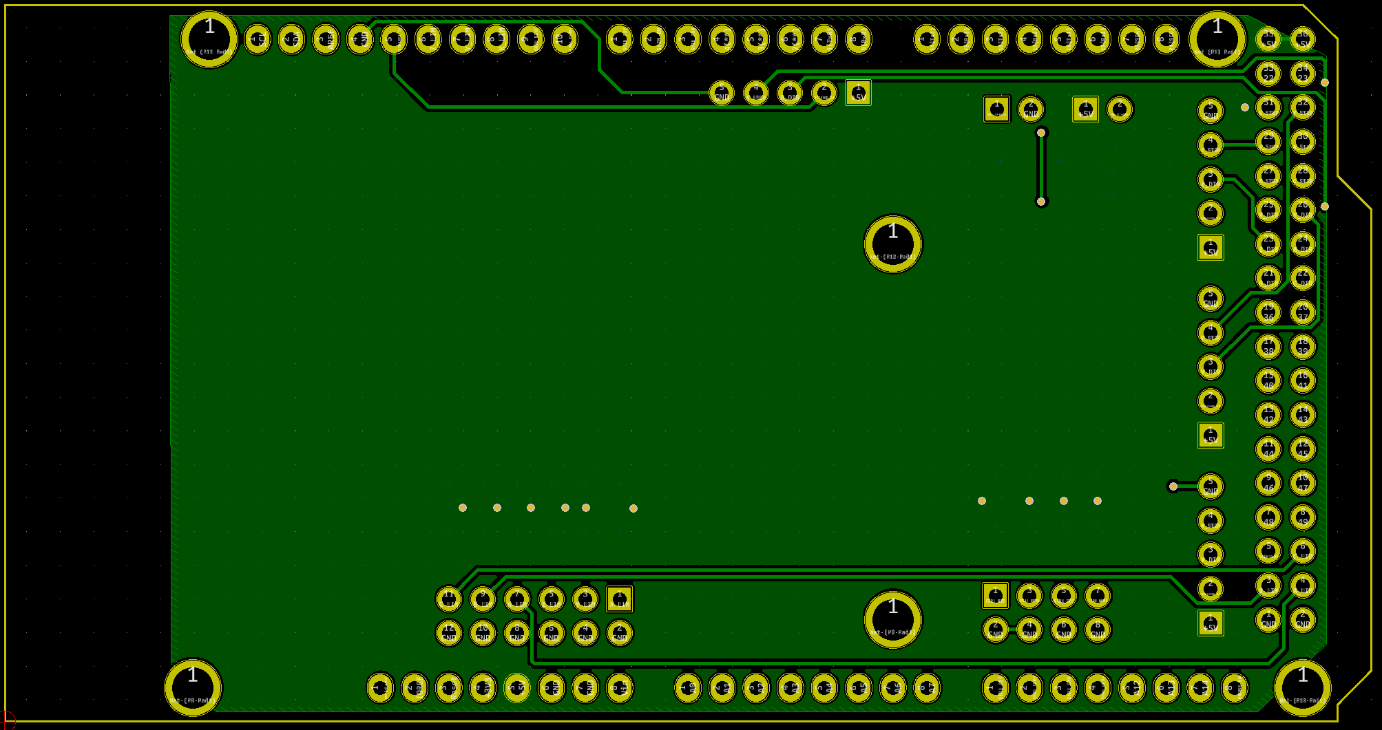
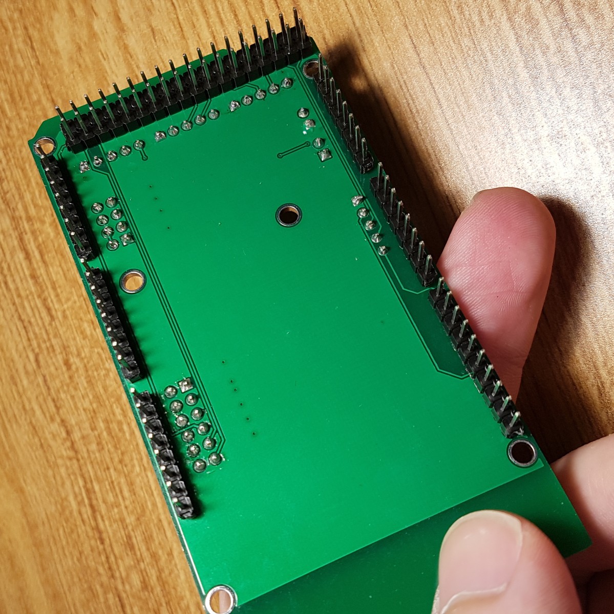
The bottom is used for a few traces and a 5V power supply pour.
Assembly
Assembly of the board was simple and issue free. A stencil was used to deposit the solder paste and then I hand placed all the surface mount components with tweezers before re-flowing. Once the surface mount work was complete, I inserted all the headers for the Mega into a a Mega and soldered the board while mounted to ensure all the pins would be nice and perpendicular to the surface. Then I flipped the board and added the headers for CNC hardware by hand.
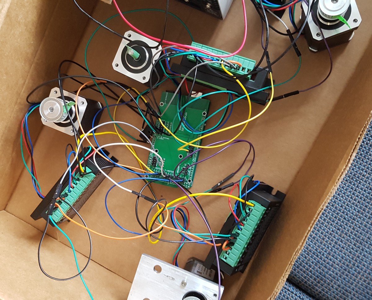
Connecting the board to the rest of the CNC hardware was achieved using standard jumper wires for testing. I then redid some of the wiring to use better wires and rely on fewer jumpers when we were done testing for more reliable connections.
Testing Firmware
Initially everything was housed in a box so it would be easier to observe all the motors when testing the firmware.
Initially the system worked with the computer software for the foam cutters. However, the project lead decided to switch the PC software we were using to another program that was more capable and easier to use. This resulted in one of our motors not working at all, but the other three worked fine. Switching back to the original PC software fixed this.
So we figured it had to do with the commands they were issuing. Comparing the output of the two programs we discovered that they were both issuing commands to the X, Y, Z axes - however the original program referred to the fourth axis as “W” while the new program used “A”, so the firmware on the Mega was discarding these instructions. We were unable to change this axis designation in the software on the PC, so I had to go and catch it in the firmware. Unfortunately I could not easily rework the Mega’s firmware from dguerizec, so I found another similar project that was also based on grbl but I could easily alter to use respond to either character for the fourth axis. This was the grbl Mega 5X project.
Once we had observed the expected motions on all the motors the system was moved to a proper metal enclosure and the motors were mounted to the CNC to see if they would work just as well once loaded. As you can see in the short video below, it was a success!
Production!
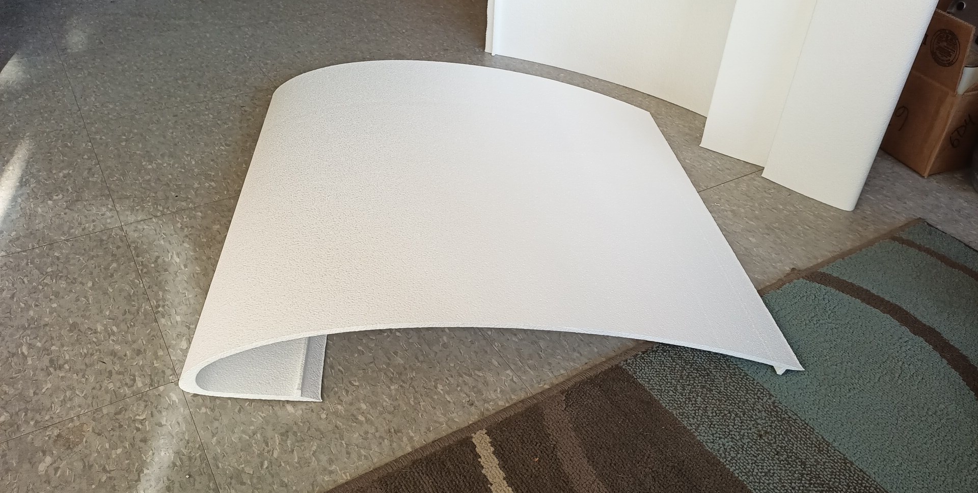
Once the system was moving as expected with the PC’s commands the team was good go and start cutting parts from foam.
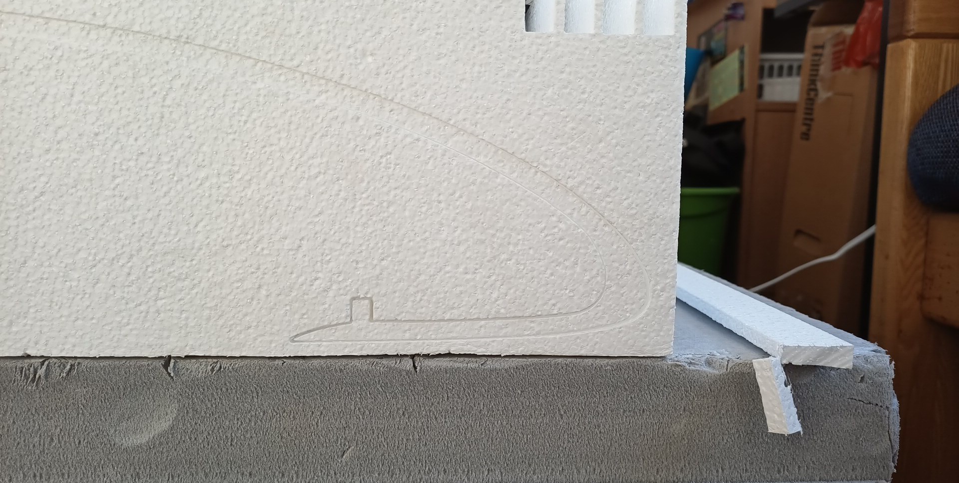
Once removed from the block we get a nice part.