Rebreather Monitoring
Table of Contents
Overview
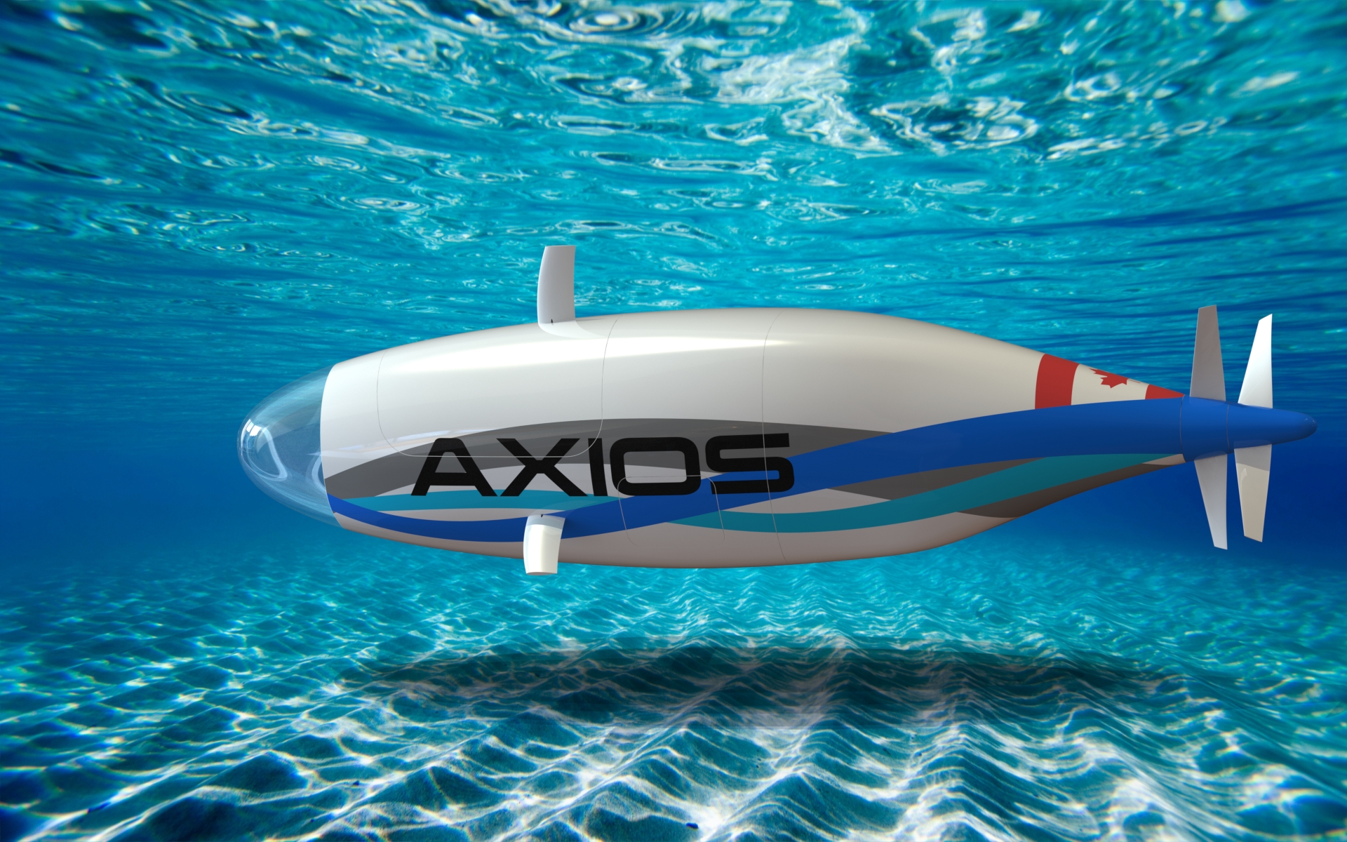
The most critical electronics system in HPVDT’s submarine project, Axios, is the rebreather monitoring system. This system is responsible for reading and displaying the current concentrations of oxygen and carbon dioxide to the rider from the sensors located around the submarine so they know how to regulate the rebreather.
In addition to the necessary reliability and accuracy of the system for safe operation of the submarine, the values needed to be easily read in the darkness and shine through the back of the mirror used for navigation.
The work on this system was split pretty evenly between me and another team member interested in learning electronics. The system has been designed and assembled. It is currently being tested before being approved for use.
Requirements
- Read and display the gas concentration from each of the
- 3 Oxygen sensors (PSR-11-39-MD), accurate to 0.1%
- 1 CO₂ sensor (MH-Z19B), accurate to within 5ppm
- Operate for hours on end
- Use a bright and reliable display method
Objectives
- Allow for the system to be calibrated without needing code to be updated
Takeaways
Interfaced with two new types of sensor output: ridiculously low voltage ranges and PWM. Both of these needed me to implement new methods of handling them I hadn’t in any of my projects before, some in hardware, others in software.
Detailed Report
HPVDT has been working on a submarine called Axios on and off for a few years now. I remember them showing it off in the clubs fair of my first year of university and thought it was a really cool project and wanted to contribute to it so it was a major factor in me joining the team in the first place. So when we decided to focus our efforts on trying to complete it (originally for the end of summer 2020) I hopped on the chance to contribute!
There are a few electronics systems I needed to prepare as the head of electronics and arguably the most critical for rider safety was the rebreather monitoring system.
The majority of previous notable human powered submarines were wet hulled, allowing fluid to freely enter and exit the hull and traditional diving equipment was used to provide the air for the riders to breathe. Axios however is dry hulled, so air stays in and water stays out. This makes it impossible to use traditional diving systems since the air released, that would normally be exhausted into the water and away would instead accumulate and build pressure within the submarine. Axios makes use of a rebreather system where the air in the submarine is recycled and chemically treated to maintain safe oxygen and carbon dioxide levels, thus the pressure stays constant at around atmospheric.
The rebreather needs to be adjusted by the rider to accommodate changes in the air composition so they need to know what the exact composition of the air is. To provide this information is the purpose of the rebreather monitoring system. To gather this information of the atmosphere in the sub there are three oxygen sensors and one carbon dioxide sensor. The rider will be informed of each sensor’s readings separately (instead of an average) to allow them to identify any potential issues with the sensor system.
Not only does the system need to accurately reflect the composition of the air in Axios, it also needs to be reliable and easily readable in the darkness of the submarine.
Circuit Design
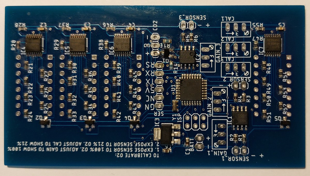
The circuit design and layout was completed in EAGLE. For the circuit design I had the teammate design the circuit in modules based on purpose that were then combined for the final design.
The overall system design is centered on an ATmega328P microcontroller, the same used in Arduino Nanos. Fanning out from it are the circuits responsible for conditioning the oxygen sensor signals, the CO₂ signal and then the displays. The entire system is powered off a shared 5 V supply generated from a linear regulator stepping down the supplied battery voltage.
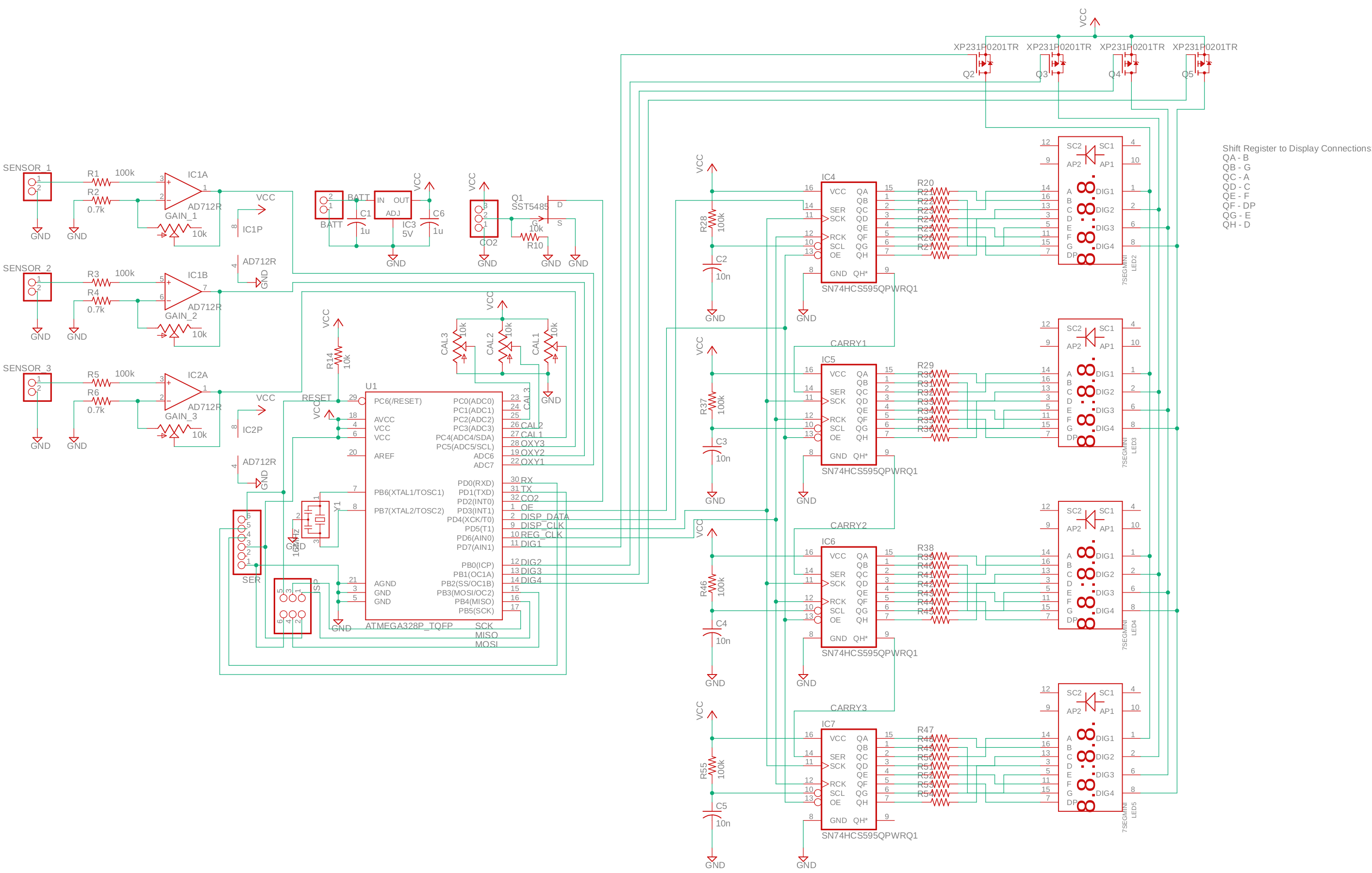
The ATmega was chosen for both our familiarity with it and having just the right amount of features we needed for this. It has an internal analog to digital converter for the oxygen sensors, interrupt pins for the CO₂ sensor, and timers needed for driving the displays. Both SPI ISP headers and serial headers for programming were put on the board.
A linear regulator was used to supply the 5 V instead of a more efficient switched mode one to minimize the noise on the supply line which may affect the amplification and reading of the oxygen sensors’ small signals.
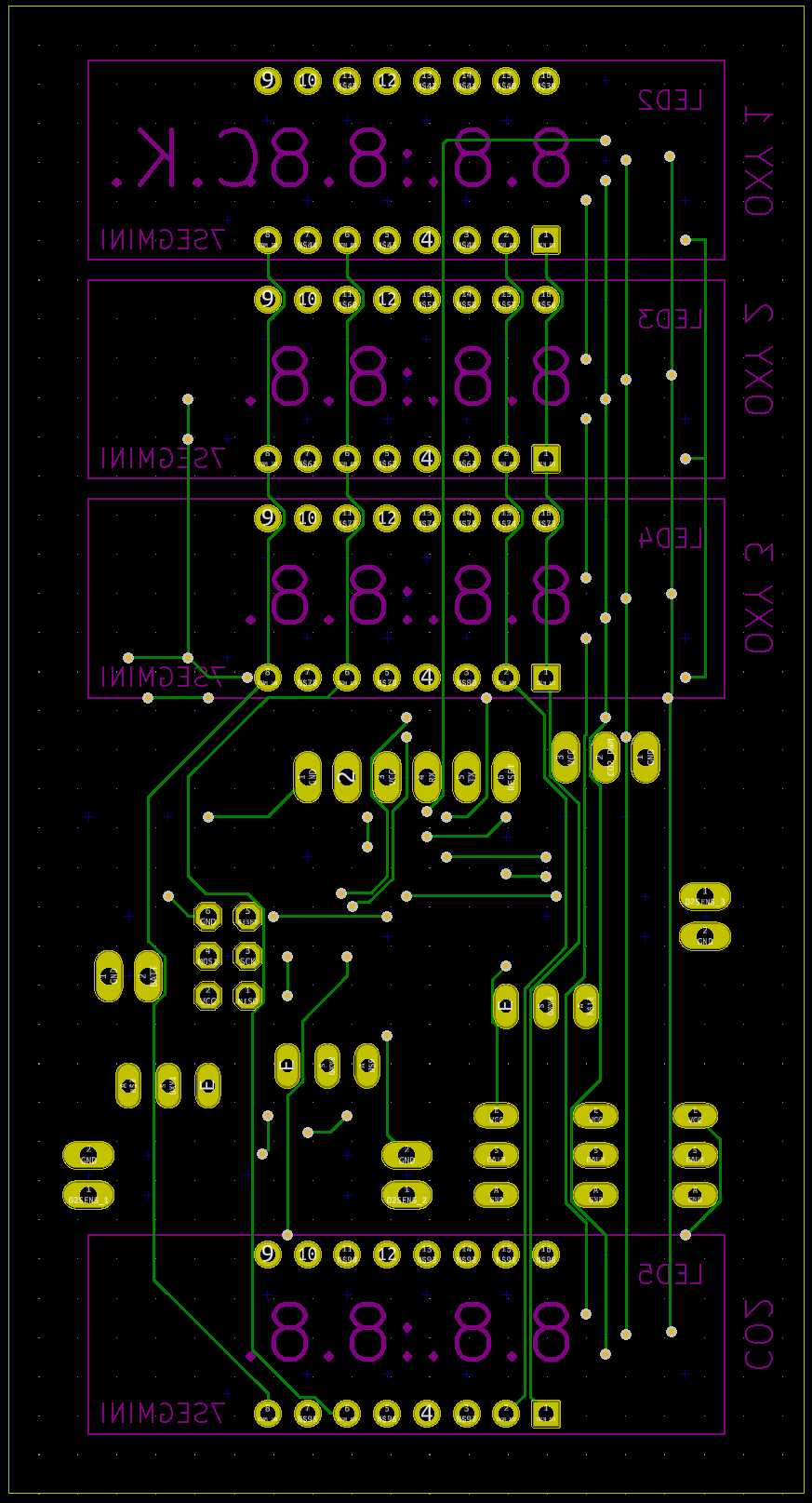
Display Modules
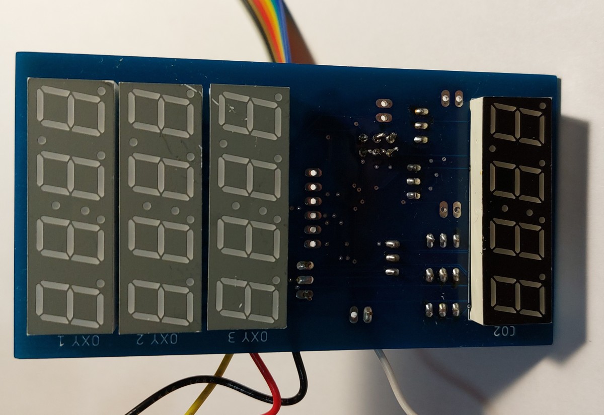
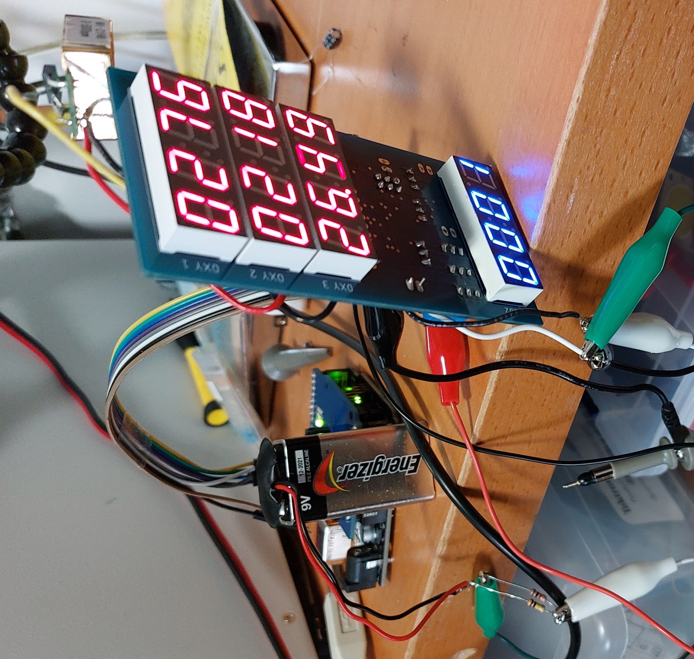
There are four displays needed for the system, each with four digits. It was decided that the most reliable way to display information clearly to the rider was through the use of LED seven-segment displays.
Each display needed 12 pins to be controlled: 8 for the segments (character + decimal point) and 4 to set which digit(s) to show. With four displays each individually controlled, up to 48 pins would be needed! This would not be feasible to control from the microcontroller directly since a much larger microcontroller would be needed, instead much of the control would be offloaded to shift registers.
Shift registers take in information serially (sequentially) on two pins, data and clock, and then output it in parallel. The basic principle can be imagined as them taking in and storing whatever the state of “data” is when “clock” is pulsed to their first slot as they move all previous data over one spot to make space for it. They can be daisy chained to form an arbitrarily long chain all controlled from the same two inputs, this allows a microcontroller to use just two pins to control theoretically an infinite number of outputs.
Each display uses a shift register to control the segments that are illuminated, so the microcontroller handles all 24 segments with just two pins. The microcontroller then uses transistors to control which digit is visible on all the displays. Thus, it is able to control all of the displays using only six of its pins! There is actually a seventh pin, used to regulate the brightness of the displays by using a PWM wave on the output enable pins of all shit registers, but it is not vital.
Oxygen Sensor System
Our oxygen sensors used for the submarine are basically open air chemical cells that produce a voltage linearly proportional to the oxygen present in the air, between 10 mV at 0% and 65 mV at 100%. The problem is that this signal is much too small for a typical ATmega328 to meaningfully read given the resolution of its ADC (10 bits, 1024 increments), even when using the 1.1 V reference instead of the 5 V.
To address this, the signal from the sensors is amplified to a larger range before being read by the microcontroller, using an operational amplifier in a non-inverting configuration.
Since the characteristics of each sensor will vary due to manufacturing and change over time with use as the chemicals are expended, the gain needs to be easily adjusted. This is done by using a potentiometer as part of the feedback loop for the amplifier allowing the gain to be increased or decreased as needed so that 100% oxygen would correspond to the maximum reading of about 5 V.
The gain isn’t the only thing that requires calibration, a low point calibration is also needed. This is because the no oxygen doesn’t produce an output on the sensor of zero volts, but rather some intermediate voltage. So a second calibration point is set using the atmospheric concentration of oxygen (about 21%) using potentiometer to produce a reference voltage for this level on each sensor. This second point is a convenient calibration point since we want to keep Axios’ environment as similar to atmospheric as possible, so by calibrating to it we can be confident the values near it will be accurate.
Carbon Dioxide Sensor Interface
The carbon dioxide sensor selected for use in the submarine outputs a PWM signal which expresses the CO₂ levels it measured, all it needs from the system in return is a pair of power connections (0 and 5 V). However the PWM signal cannot be fed into the ATmega directly because the sensor outputs a 3.3 V wave, so it wouldn’t register properly on its 5 V logic.
To accommodate this difference, a level-shifter is needed to convert this 3.3 V signal into a 5 V one. A basic one is used for Axios, just a transistor controlled by the sensor PWM that pulls down on pin on the ATmega when the PWM is high. The only inconvenience to this simple arrangements is that the signal will get inverted so the PWM highs will be output as lows, and vice versa.
Layout
Other than providing some basic requirements to the teammate related to size limits and display positioning, the layout was entirely their design. There was no need for mounting holes since the board would be adhered into place.
They prepared a display module layout that was repeated for each of the four displays, the three oxygen ones at the top, the CO₂ one at the bottom, and the remaining electronics in the gap between these display banks.
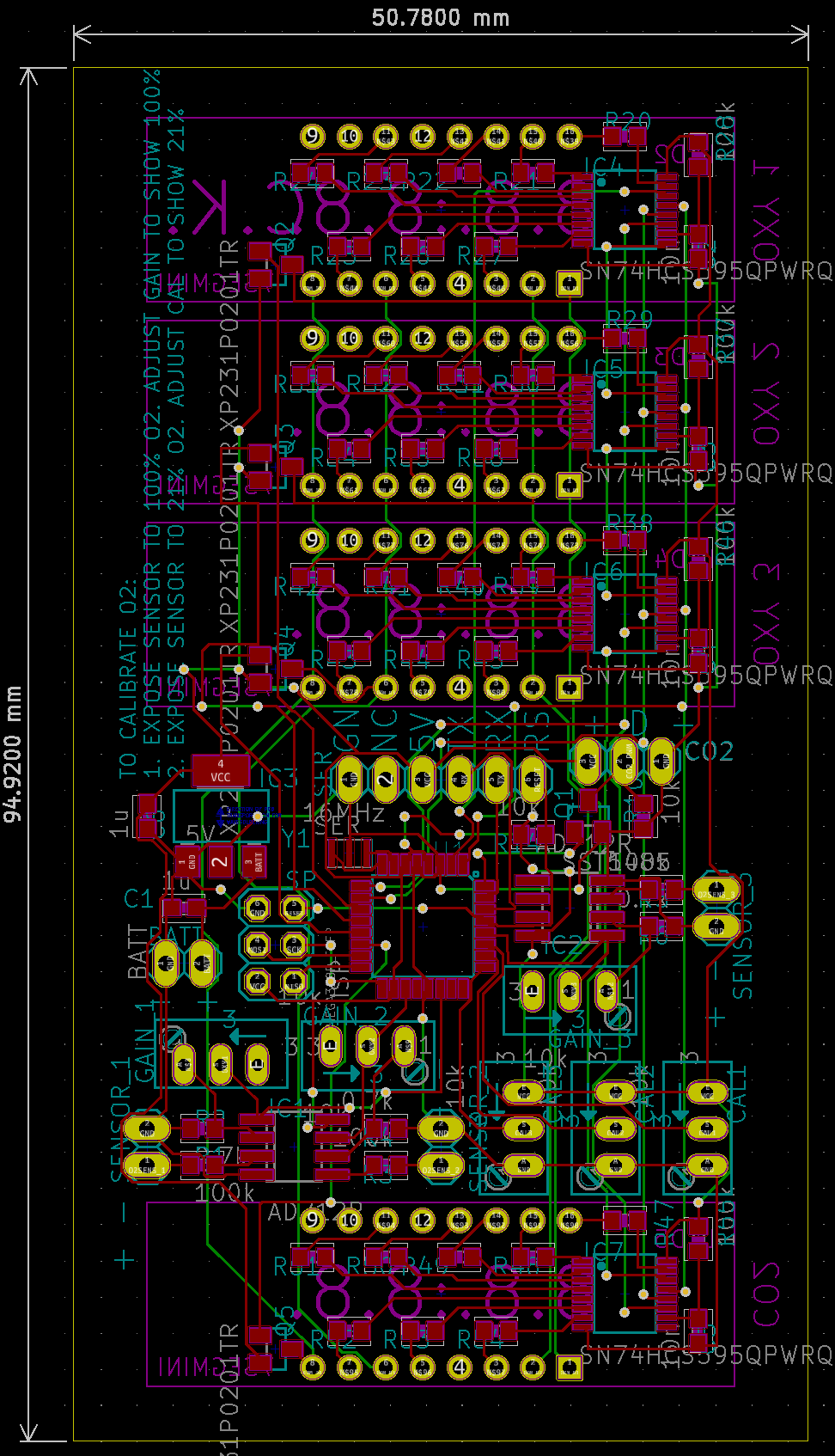
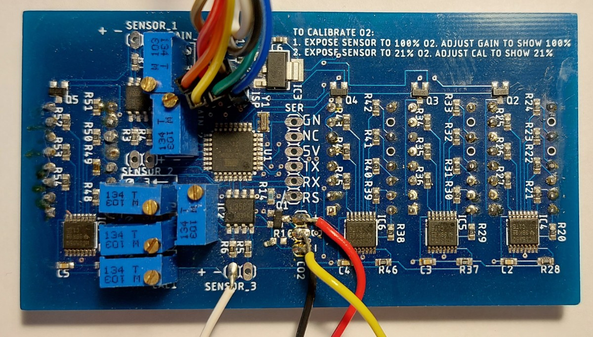
All the surface mount parts are mounted on the front, as well as the potentiometers (although they can also be mounted to the front). In addition to the components, there were some instructions added to the silkscreen to instruct users on how to properly calibrate the oxygen sensor system should I not be present.
There is not much going on on the back side of the board specific to it, other than being where the displays mount to.
Assembly
A standard mixed part affair, just that the teammate did the assembly under my supervision instead of me doing it myself.
A stencil was used to place the paste on the board, the surface mount components were all placed and reflowed. Before moving to placing and soldering the through hole components the board was checked for any shorts caused by solder bridging some of the leads on the ICs. Luckily there were none present.
My teammate then soldered the through hole components (displays and potentiometers) and board assembly was complete. I then soldered wires for testing and programming the microcontroller myself before I started coding.
Programming
I handled the programming of the system myself.
The board is programmed entirely in the Arduino IDE as an Arduino Nano. Its code is prepared in C++ and then uploaded using an In-System Programmer (ISP), which originally was another Arduino I prepared for this purpose but I now possess a proper commercial one.
Display Code
The display code is based off what I did for the scoreboard project. However instead of controlling the segments directly from pins of the microcontroller, the microcontroller would be passing settings to the shift registers that controlled the segments for each display.
To communicate the microcontroller would operate the data and clock lines for the shift registers. It would start by setting the two lines low, then based on whether or not a segment needed to be on - setting the data line, before finally raising the clock line and pushing the data into the registers. This was done for each bit of the displayed character for each of the four displays present.
// Output new segments to shift registers
for (byte displayIndex = 0; displayIndex < numberOfDisplays; displayIndex++) {
  // For each digit output push out segments bit by bit

  for (byte bitOut = 0; bitOut < 8; bitOut++) {
    PORTD &= B11001111; // Clear data and clock

    // Set data pin as required
    if ((displayArray[displayIndex][currentDigit] & (1 << bitOut)) == 0) {
      // The segment meant to be off (0)
      PORTD |= B00010000; // Set segment to be off (high)
    }
    else PORTD |= B00000000; // Set segment to be on (low)

    PORTD |= B00100000; // Set clock high to push data in
  }
}
Oxygen Reading
Oxygen readings are generated from some linear interpolations. The interpolation line is set with one point just below 5 V for the maximum (100%) reading, then another voltage set by potentiometer for each sensor at atmospheric conditions (~21%, so ~1 V). The function used to get oxygen readings fits the voltage-oxygen line in the form of \(y = mx + b\) and then uses it to derive what the oxygen value is by rearranging to \(x = (y - b) / m\).
float oxygenRead(byte sensor) {
  // Oxygen value calculations
  // Get analog values
  float OR = analogRead(oxygenSensor[sensor]);          // Oxygen sensor reading
  float cal = analogRead(oxygenCalibration[sensor]);    // This is the calibration value.

  // Math
  float b = cal / 21.0;
  float m = (1010 - cal) / 79.0; // This is the gradient (slope) of the function.
  float oxy = (OR - b) / m;     // This is the oxygen value.

  return (oxy);
}
The reason I used a point slightly below the actual maximum of the range, 1010 instead of 1023, for the 100% mark is so that during calibration of the oxygen sensors there is clear feedback that the gain is set too high, since over 100% will appear.
Carbon Dioxide Reading
The carbon dioxide reading is PWM based, so the width of the output high phase corresponds to the concentration of CO₂ detected by the sensor. This wave is connected to an interrupt pin on the ATmega which toggles on any state change so it marks both the start and end of a PWM wave.
The signal has a period of about a second according the the manufacturer’s data sheet, and the CO₂ level is encoded using the following formula, \(CO₂ = ppm span \times \frac{T_h - 2ms}{T_h + T_l - 4ms}\), where \(T_h\) and \(T_l\) are the periods the wave was high or low respectively. The measuring span (ppm span) of our model of sensor is 2000 ppm. This results in the following interrupt routine for the CO₂ input.
void CO2Interrupt () {
  // Based on time high and low for a PWM cycle, in milliseconds (total period ~1004ms)

  // NOTE THE PWM IS INVERTED BY THE LEVEL SHIFTER, HENCE THE SEEMINGLY CONTRADICTORY PIN STATES

  unsigned long currentTime = millis();

  if (digitalRead(CO2Sensor) == HIGH) {
    lastFalling = currentTime; // Mark falling edge of PWM
  }
  else {
    // Rising edge, start of a new pulse

    // Calculate CO2 level from last pulse
    // CO2 = ppm span * (Th - 2ms) / (Th + Tl - 4ms)

    unsigned long timeHigh = lastFalling - lastRising;
    unsigned long timeLow = currentTime - lastFalling;

    CO2Level = CO2Span * (timeHigh - 2);
    CO2Level = CO2Level / (timeHigh + timeLow - 4);

    lastRising = currentTime; // Update rising time
  }
}
Note: the CO₂ sensor recommends a few minutes to warm up before results can be used. To communicate this to the rider I have the display for the CO₂ reading show a count down for three minutes after powering on before finally showing a CO₂ reading.
Testing
Testing was completed by me and is largely complete, except for proper testing of the oxygen sensors. Most of it has gone well, I had some hardware issues that were revealed with testing the CO₂ sensor but it has been patched over now.
Display Tests
The display code works fine, I have been able to show any arbitrary values on all four displays and adjust their brightness as I please.
Carbon Dioxide Testing
When I assembled the system so the carbon dioxide sensor was connected, I found that the CO₂ sensor appeared to be unresponsive and the microcontroller was unable to get any data from it to use. Not exactly the plug and play experience I was hoping for.
I took out my oscilloscope and checked if the sensor was actually producing a signal. Not only was it producing a proper output signal, it also informed me that my workspace needed some fresh air! I then probed the output of the level shifter, this was stuck high. This made no sense to me so I consulted the schematic, and it turned out the issue was with the transistor used for the level shifting.
In the design I wanted to use a certain N-channel MOSFET I had selected, however it didn’t have a part in the default libraries included with EAGLE so I wanted to use a similar MOSFET that was included that came in the same packaging and had the same pin out, just a different name and internals. I had either failed to properly identify this equivalent, or had accidentally been off when entering the name since the part used in the schematic and on the board failed to match the one I purchased and installed. Thus the level shifter was not working since the signals were all going to the wrong pins.
Initially I wanted to remedy this by purchasing the actual part specified and using that on the board. Unfortunately it was obsolete and I couldn’t find suitable replacements for it. In the end I went ahead and moved the level shifter off-board by soldering the MOSFET to the CO₂ sensor and replacing the transistor on the board with a short between the CO₂ data line and the input on the microcontroller.
Oxygen Sensor Testing
Testing the oxygen sensors properly is the last remaining tasks for this project before installing it in the submarine. The reason we haven’t done it yet is because unlike the CO₂ sensor which is an electrical sensor, the oxygen sensors use chemical reactions and thus have a limited operation life so we will wait until we are near the deployment of the submarine to purchase them and use them in testing before reusing them for actual trials of the submarine.
However, it is still possible to test the system using a controlled voltage to simulate the behaviour of the oxygen sensors as far as the system can tell. So this is what I did to perform an initial validation of this design.
The test design was simple: connect some controlled voltage source to the system, power the system and verify that adjusting the trimmer potentiometers affects the results as expected.
Input Issues
Right off the bat I had some issues, when I connected my voltage source for the oxygen sensors, the system read 0. After a bit of review, I found out that we had accidentally reversed the labelling of input polarity. Luckily the input was only a few dozen millivolts so no damage occurred to the system. Once I reversed the wires, the system was working but there was significant noise to the readings.
With the inputs connected properly, I tried to adjust the gain since it was a too low. The gain topped out much lower than I expected, after checking the schematic everything was assembled correctly. However I had set the trimmer to be 10 kΩ instead of 100 kΩ which is why the gain achievable was an order of magnitude lower than expected. After replacing the 10 kΩ trimmers with 100 kΩ I was able to amplify the signal properly.
Noise Issues
Initially I used a function generator outputting a DC signal directly in the tens of millivolts for this, but it had several millivolts of noise to it that made it hard to monitor properly. So I switched to using a 9 V battery with a resistor voltage divider (in hindsight I realize I could have done the same with the function generator, alas.) This provided a rather smooth input for the system. This reduced the noise on the reading but there was significant lingering noise.
I was curious what the values the system was reading were so I set the system to show the raw ADC reading for the input on the top display, the raw input of the calibration trimmer reading on the second, and then the calculated oxygen percentage on the third. The bottom screen showed the digital state of the CO₂ line.
I did this to help my debugging and eventual calibration. I was hoping that the values were switching between between only a few values and there was an issue in floating point and integer math. Unfortunately the raw input was swinging wildly. With no real idea what was causing this I started by monitoring the power supply lines for noise, and boy did I find it.
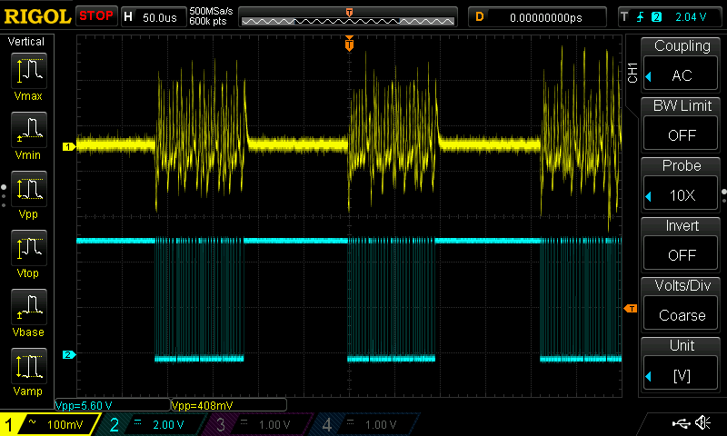
It turns out that the noise was related to the switching related to display updates. I probed the clock line used for the displays to see if it lined up and you can see it on the figures.
It struck me as odd that there would be this much noise in the system, so I checked the schematic. Turns out that we had not included a single decoupling capacitor for the ICs. Oops, well that probably explains a bunch. It was about two years ago so I guess I neglected to consider them. I added a few capacitors, including ones directly on the op-amps to help out and they did noticeably reduce the effects of noise.
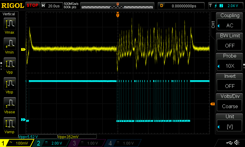
My final fix to address this noise issue was to have interrupts disabled before taking oxygen readings, so that the switching wouldn’t affect it. After disabling the interrupts I have the system also wait a few microseconds to ensure that any trailing noise from the switching disappears.
noInterrupts();
delayMicroseconds(10); // A bit for noise to dissappear

int OR = analogRead(oxygenSensor[sensor]);          // Oxygen sensor reading
int cal = analogRead(oxygenCalibration[sensor]);    // This is the calibration value.

interrupts();
With these changes, I am confident the system will work correctly once the trimmer potentiometer are set correctly to the oxygen sensors used.
Current Status
With the board assembled and largely programmed, all that remains before deploying the system is properly testing the system on battery power with the chemical oxygen sensors instead of my simulated inputs.
Revision?
I have identified a couple issues with my tested that could be rectified with a hardware revision. I don’t think I will actually bother with this since I already have assembled the one board and a spare. Anyway here is a compiled list of the things I would amend in the next version if I make it, ordered roughly in terms of importance to me.
- Use a proper and common MOSFET on the board for PWM level shift for the CO₂ sensor
- Add 100nF decoupling capacitors to each IC
- Specify the right trimmer potentiometer value for gain (100 kΩ)
- Fix the labelling of the oxygen sensor pins
- Re-arrange the layout
- Move sensor connections to the edges of the board
- Put the trimmer potentiometers in a nice labelled grid
- Add more space around the ISP header to fit a potential IDC connector
- Remove the serial programming header, or make it surface mount