Telemetry
Table of Contents
Overview
HPVDT’s vehicles collect data about their state and relay it to their riders in real time. I developed a general system that could used to broadcast data out of the vehicle to a base station so our crew could also view data in real time instead of going through logs afterwards to analyze performance.
The system is based on nRF24L01 modules that support a range of about 1 km with direct line of sight at a bandwidth of couple dozen kilobytes per second, which is a far more than adequate bandwidth for our purposes.
I used Blueshift as the context to develop this for, but it was prepared in a modular way so that it could be easily redeployed in future projects.
Requirements
- Communication with vehicles with 400 m direct line of sight
- Based on the distance our trail van is behind our speed bikes
- Have communication bandwidth of 2 kbit/s
- Have a modular code-base/library
Objectives
- Range of 750 m with direct line of sight
- Bandwidth of 20 kbit/s
- Bi-directional data exchange
Takeaways
- Double check voltage tolerances of your parts!
- Preparing a useful UI is much harder than just a functional one
Detailed Report
For all of the team’s vehicles more and more data was being gathered, however it is in most cases only visible to the riders when it is measured. For anyone else to make use of it it needs to be logged and read later.
As head of electronics I was interested in seeing if we could develop a generic system to help us exchange data wireless on a reasonable financial and power budget.
Wireless Modules
Given the specialization and engineering that is required of most advanced radio systems I decided to use some commercial hardware modules to achieve to handle the communication. After some research on available products and the projects that used them I settled on using the nRF24L01 line of wireless communication modules. My reasons for selecting these were that they met all our requirements and objectives on paper, as well as being pretty cheap and there were many example projects to draw ideas from.
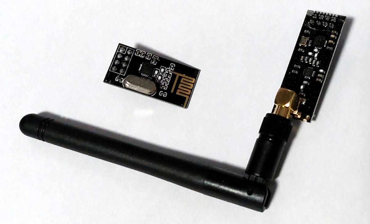
There are two variants, the basic ones with a printed antenna and the other with a low noise amplifier (often referred to as nRF24L01+LNA). Other than the obvious difference in range and power consumption, they are identical and interface with the system indistinguishably from one another.
Hardware Design
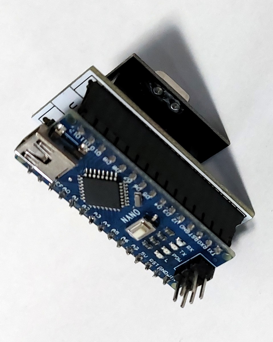
Since we were using commercial modules there wasn’t much need for any additional hardware other than a development board with SPI support and a 10 uF capacitor for the module. For development I selected to use and Arduino Nano since I was familiar with them and their size small size helped reduce clutter in my workspace.
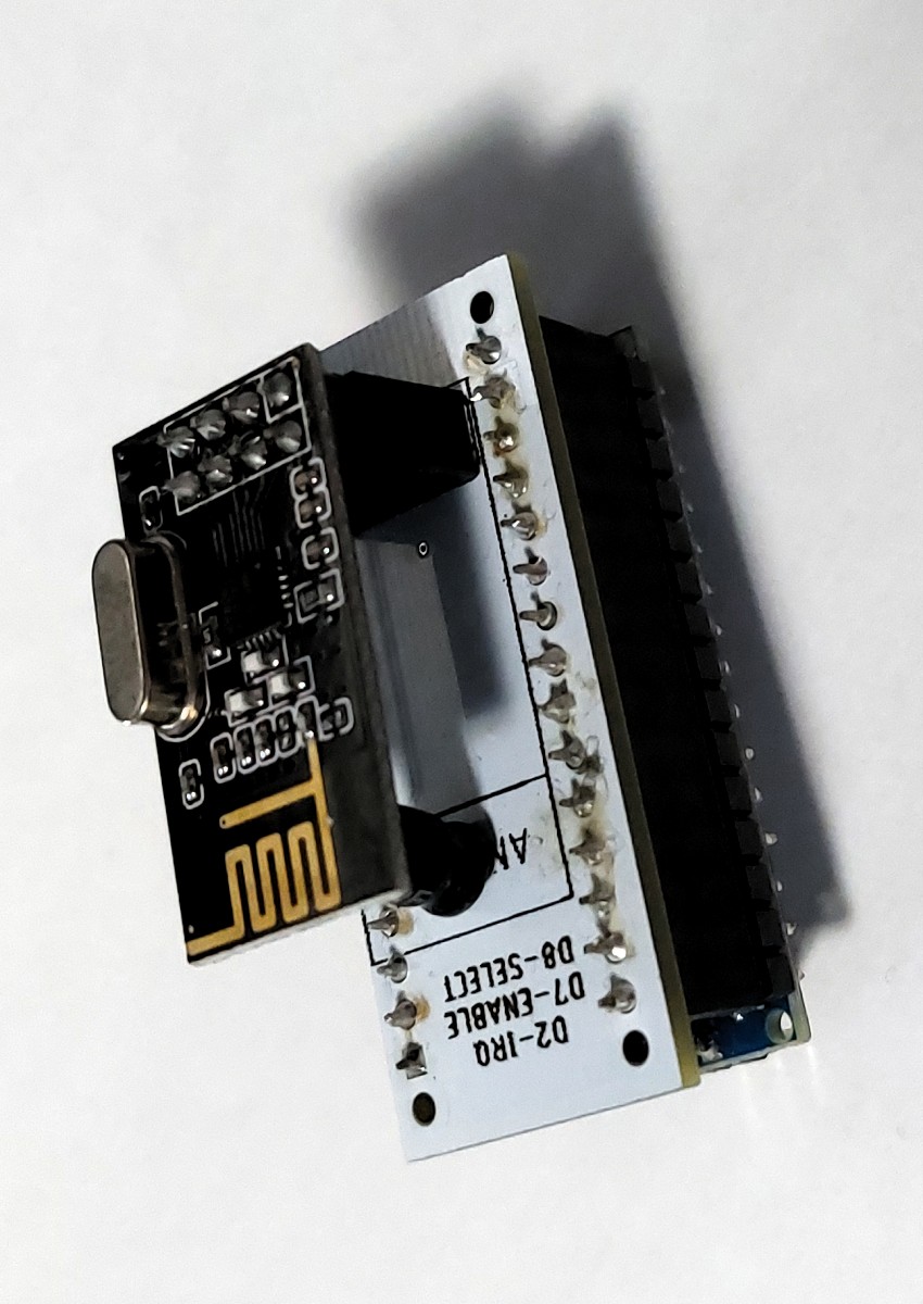
I designed a small adapter board to connect the radio modules to the 10 uF capacitor and the Nano to make it easier for myself and others to test and develop telemetry code without having to worry about wiring issues.
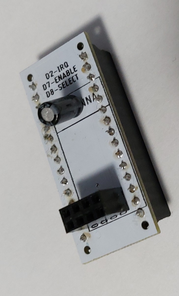
Not much to mention about it other than the capacitor was placed to support the cantilevered end of the radio module if it were to be pressed.
Coding
The focus of this project was the code. There were three bodies of code prepared:
- Microcontroller code for receiving or sending
- A dashboard to show received data (to be used in the pit or chase vehicle)
- A dashboard to configure test data to send
The microcontroller code would be written in C++ in the Arduino IDE. The dashboard however would be written in the Java-based Wiring language used in the Processing IDE.
Microcontrollers
In the system the microcontrollers would be the hardware directly communicating with the nRF24s, so my code for them made use of the available nRF24 library, amply titled “RF24”. This greatly sped things along with using the hardware since it provided useful functions and some examples.
The way the nRF24 modules work is that each one can tune into a certain frequency called the “channel” of the about 125 available. One these channels the nRF24s use “pipes” to exchange data. These pipes act like a subject for the message, there can be an unlimited number of different subjects or topics on a channel but the modules can decide which ones it wants to subsribe or write to. A single module can tune into only one channel, on which it can write to one pipe at at time, but can listen to multiple. However, they can only be acting as either a “listener” or “sender” at a time. So in my system I set one Nano to run as a receiver and the other as the sender on a shared pipe with the following code.
radio.begin();

radio.setChannel(100);            // Radio channel frequency used

if (recieverRole == true) {
  // Reciever
  radio.openReadingPipe(1, pipes[0]);
  radio.startListening();
}
else {
  // Sender
  radio.openWritingPipe(pipes[0]);
  radio.stopListening();
}
In addition to the code configuring the roles of each circuit/module, there was also some configuration of the radio hardware that needed to be done, such as output strength and bandwidth. This was the same for both ends.
radio.setPALevel(RF24_PA_MIN);   // Low power, raise if a decoupling capacitor is added
radio.setDataRate(RF24_250KBPS);
radio.setRetries(5, 15);         // Smallest time between retries, max no. of retries
There is an issue here though, there isn’t a clear way for the systems to exchange data both ways since one is listening to the other that only sends.
To get around this, I initially made an effort to have module alternate roles as needed, basically listening until they needed to write. This worked somewhat, but I had issues where messages would be lost if the modules were changing roles all the time, especially if a string of messages were sent at once.
The method I implemented in the end made use of dynamic acknowledgements. Although the listener is not meant to send any data on a pipe, it can send an acknowledgement message to a sender to inform them the message made it to them. Normally these are automatically generated and devoid of any data themselves, however by adjusting some settings one can load these acknowledgements with their own data so the sender can read a response. This eliminated the need for me to alternate the roles all the time. To get this set up it needed the following code.
radio.setAutoAck(0);            // Ensure auto-acknowledgment is disabled
radio.enableAckPayload();       // Allow optional ack payloads
radio.enableDynamicPayloads();  // Let me stuff acknowledgements with my own data
To send data as an acknowledgement packet, I had to use the radio.writeAckPayload function on the receiver. It takes in the target pipe to send the acknowledgement packet on, the message itself (as a C string (null-terminated character array)), and the length of the message in bytes.
radio.writeAckPayload(pipeNumber, outputMessage.c_str(), messageLength;
On the sender’s end, the acknowledgement message would be treated as a normal message to be read using the radio.read command. When the sender would like to send a message it would simply pass it to the radio.write function much like the radio.writeAckPayload function, except a pipe is not specified since it uses the pipe previously set with radio.openWritingPipe.
With these basics established I prepared some code to wrap these into nice functions to use in my future work. I made a function that could be called for setup, and others to receive and send messages. I used a global constant to keep track of if a system was meant to be a receiver or sender so it would use the right code for setup and receiving.
Sending Dashboard
This was one first foray into Processing in a long time, the previous one being in the summer of 2017 for a personal project that I lost interest in shortly after starting.
The concept was simple, I would have a bunch of sliders for all the different data fields I was interested in that I could adjust and the program would send their values periodically to the Arduino over serial. I added a drop-down menu to pick which serial port the Arduino was on and a button to start the process.
To communicate with the Arduino I decided to reuse the communication scheme I used for TITAN RPi-Microcontroller communication. This would send each data field as its own message; first byte data type (e.g. speed, “S”), second would be data length (e.g. 4 [characters], “#” (this is explained fully in the TITAN page)), and then the data (i.e. “59.4”) to make a message like “S#59.4”.
Although not directly super useful for the rest of the team outside the scope of this project, the sending interface could still be used for the development of other systems since it used the same data structure our vehicles have used since TITAN to communicate data between microcontrollers. This is shown in my Blueshift telemetry demo under deployment.
Receiving Dashboard
The receiving dashboard was the sending dashboard but instead all the inputs were disabled and they were used to display data sent out of the Arduino.
Unlike the sending dashboard this one would likely find use in the future outside this project on base stations either in pits or chase vehicles at races.
Testing
For testing the microcontroller code, I simply had each Nano act as a pass-through. They would receive data to send from the host PC (instead of data it collected itself) and forward received data to the host PC over serial communication. This is why I wanted to make the interfaces for both testing and sending code to aid in testing this with multiple data channels at once in a more user friendly way than a scrolling data stream in a terminal.
For most of my development I was working with the smaller non-LNA versions of the modules since they drew less power than the LNA versions. The LNA versions could draw enough current during sending that they would overload the voltage regulators in the Nano and cause power-related glitches for either themselves or the Nano. Using the smaller modules was acceptable since I was anyways only developing and testing the code with two modules about a metre apart, and the code would work the same with the LNAs.
Deployment
These have yet to see proper field deployment since this was developed at the start of the COVID-19 pandemic and we have yet to field a vehicle. I have however done some testing with the modules and my computers to good success.
There hasn’t yet been a proper long-distance capabilities test, but I’ve seen others use them and record good performance so I am confident they will hit the mark.
I have a video of me using the system to test my new C-based Heads Up Display (HUD) for Blueshift. In the video it demonstrates the sending panel but the data is shown on the HUD instead of my dedicated receiving panel.
Note: I forgot to mention in the video but the reason the overlay appears undersized is because it is designed to be put over a 720p video feed, which is the resolution used in the vehicle. However for testing the camera was outputting 1080p to match my monitor’s resolution.