TITAN 2019
Table of Contents
Overview
For our new entry to the World Human Powered Speed Competition (WHPSC) in 2019, TITAN, our team wanted a new video system for the vehicle. This system is vital because it is the only way our riders can know what is outside and steer because we do not have normal windows - primarily to improve our aerodynamic performance. Not only was the system meant to provide a live video feed of the surroundings, but also overlay the feed with data about the bike’s state, namely speed.
This system was meant to be an upgrade from the system used on our previous vehicle, Eta Prime. The main changes were the transition to a digital video system based around Raspberry Pis and adding an additional rear facing camera for the rear rider.
Although the hardware was completed in time for the competition, I was unable to thoroughly test it. Some issues were encountered so the crew at the competition reverted to the Eta Prime video system since I was not present to remedy these problems myself.
Requirements
- Have three displays, each running a separate video feed
- One front facing “main” display for front rider
- One rear facing “secondary” display for rear rider
- One front facing “spare” display as a redundant video feed for the front rider (does not display bike data)
- Gather and relay the following critical data to the riders
- Bike speed
- Distance travelled
- Cadence (rate of pedalling) per rider
- Battery level
- Video feed must be stable and run at a minimum of 30 frames per second
Objectives
- Use digital cameras
- Gather and relay the following data to the riders
- Rider heart rate
- Ambient temperature and humidity
- Stream data to chase vehicle
- Record video feed
- Log all collected data
- Inform users on the estimated “performance” of the run relative to expectations
- If the conditions were favourable inform the riders we were expecting a performance over “100%” so they would know to try their best
- Likewise warn the riders if the run is unlikely to be in our favour and spare their energy
Takeaways
Testing was the critical failure on my part in this project. Had there been more time I likely would have caught the issues and tried to correct them before competition. I compiled feedback from the crew regarding both issues and suggestions that they felt would improve this system and others in the future.
As for personal takeaways, this project was my first large project that used Python, so I learned a lot about it. I found it quite nice to use, if a bit fussy due to its structured whitespace. My only issue was that due to the nature of an interpreted language, I had issues where I was calling functions incorrectly but was only told so when I ran into them, one by one.
It also was my first project that made use of a microcomputer, the Raspberry Pi. I had used one before, but it was mostly a curiosity rather than a proper tool in my eyes. In this project I came to learn about how to interface hardware with it and some of the cool features it had that could offload some complicated processing from microcontrollers. I also learned to respect some of its limitations such as its latency and slow output control.
I’m looking forward to revising the system and using my gained experience in other pursuits both for the team and my own.
Detailed Report
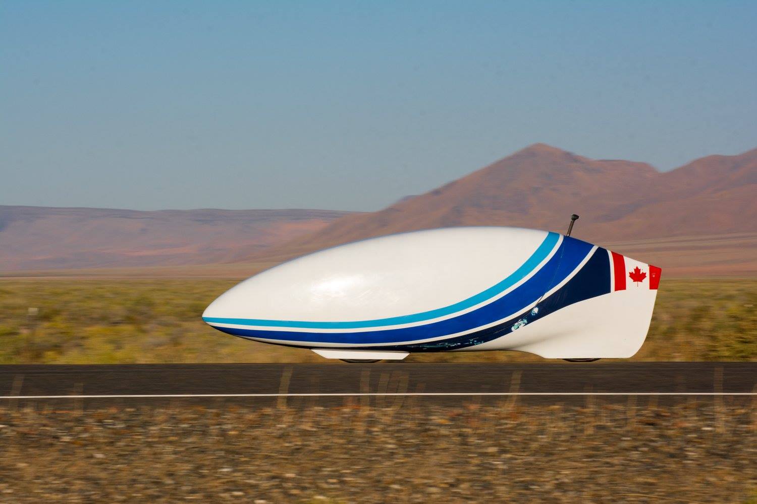
For our high performance speed bikes we pioneered the use of a video feed in place of a conventional window to see out of our vehicles. This approach provides us with a couple of advantages, namely improving our aerodynamics by allowing more recumbent riding positions for our riders (closer to laying down than sitting) which decreases our frontal cross section, and the removal of a window removes numerous seams that could contribute to disturbing laminar flow over the remainder of the fairing increasing drag. Thanks to optimizations like this, we are able to have our speed bikes exceed speeds of 120 km/h! Eta Prime currently holds our record at a hair over 130 km/h!
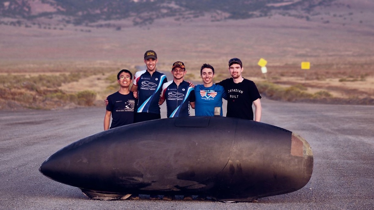
In the place of a window a camera in a mast is placed outside the vehicle and the camera’s view is relayed to a display inside the vehicle for the rider(s). On TITAN the mast is the white protrusion midway along the top, Eta Prime the black mast towards the end along the top.
This camera is vital as it is the only way for the rider(s) to see their surroundings. Should it fail, the rider(s) only have a few seconds of stability (even aided by radio instruction) before they will inevitably crash following a vision outage. In addition to the necessity of the system to operate reliably for our speed bikes to compete, they need to be responsive enough to allow for rapid corrections and to prevent rider discomfort.
The vision system is also used to relay information about the vehicle to the riders, like speed, using overlays on the video feeds. This makes it convenient for the rider(s) to quickly check how the ride is going since they do not have to shift their focus from the screen to do so.
Unlike all our previous speed bikes, TITAN is a tandem vehicle. The riders sit back to back, with one facing forwards and the other backwards. The team thought it would be wise to add an additional screen to the usual “main” and “spare” arrangement, for the rear rider. This rear screen would receive a video from a rear facing camera in the hopes of preventing potential discomforts of them moving “backwards”.
Overall System Design
With the system’s purpose outlined to me, the only other remaining suggestion/guidance I was given related to the design was to use Raspberry Pis (RPi) and Raspberry Pi Cameras (PiCam) as the foundation of the system. Since they had used these before successfully with Eta Prime.
At the time, the RPi Model 3B+’s were the newest version available, so I purchased these as well as several cameras for testing. Each RPi could only connect to a single camera and a single display, so I had to use three for the whole system. This made it harder for me to distribute data around the system since I was used to only having one or two microcontrollers in a system, but not three microcomputers with a yet unknown number of microcontrollers.
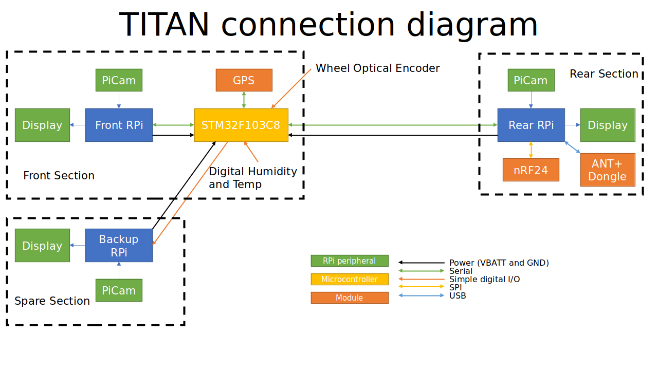
I decided to put a single STM32 microcontroller in the centre of the system to serve as a router of information in the system. It would communicate with the two data displaying systems digitally so data could be quickly exchanged as well as making use of its other hardware to collect some data itself to provide to the system.
In the end the basic block diagram was drawn up to be the following. My choices will be explained in greater detail in the sections that follow.
Raspberry Pis and Pi Cams
These were mainly used because of the recommendation to use them from the project lead. Even without his recommendation, I probably would have ended up using RPis (if not the PiCams as well) given their ease of use and wealth of community support. The purpose of the RPis was primarily to take the video feed from the cameras and display it through their HDMI output, overlaying the feed with information it collects from the system or itself.
This community of people also using their RPis for similar purposes was immensely useful for me to refer to their work and try to implement it in this project, notably with the ANT libraries used to collect biometric data from the riders’ devices.
Displays
These were generic LCD panels and driver boards one can purchase online. Our primary concerns when purchasing these were size, resolution, refresh rate, and cost in roughly descending order of importance. I did not handle purchasing the ones we used. All that I really cared about was their supply voltage and that they had support for HDMI.
All the displays ordered had HDMI support and I found through testing that they had built in voltage regulators that could accept the entire operating voltage of our selected batteries. This meant I could simply connect the battery to the displays and they would work, no intermediate regulator needed.
Batteries
The project manager requested that I design the system to run off LiFePO4 chemistry-based batteries instead of the more conventional Li-ion variety. His reasoning for the request was primarily that these batteries fail in less catastrophic ways and he would like to ensure the safety of the rider(s) as much as possible in the enclosed fairing.
This required no effort for me to accodate in the design since all systems directly supplied by the 11.1 V Li-ions we previously used, would also accept the 9.9 V LiFePO4s I selected.
Microcontroller
The microcontroller’s purpose is to collect and distribute data about TITAN as needed. The microcontroller I selected to use in TITAN was the STM32F103C8B. I had been playing with some development boards for these for some time, and was comfortable using them. They are more powerful than most of their ATmega counterparts used in Arduino boards. The feature that really sealed the deal for me is that the STM32 has not one, but three hardware UART serial ports which is perfect for this system. One line to each of the RPis that need to exchange data, and the third to the serial based GPS module.
Using a microcontroller in the system is also helpful for improving the real-time data collection performance of the system. The nature of microcomputers leaves them pretty slow to reacting to external stimuli and the RPis are no exception, the STM32 however like most microcontrollers is not running the overhead of an operating system and is thus more responsive, this is vital to keep track of the wheel’s speed which has the encoder pulse every few milliseconds at top speed.
Sensors
There was a lot of types of data collected on TITAN, I’ll be listing the hardware I used and what data it gathered. They all connect to the STM32 with the exception of the ANT+ module which is placed in the rear RPi since it needs a USB connection. It goes in the rear so if data collection with the dongle crashes the rear screen it does not lead to a critical failure for the main screen.
- Resistor voltage dividers
- Battery levels - Used to divide the different battery voltages down to safe levels for the STM32 to measure
- DHT22 (Digital Humidity and Temperature)
- Temperature in vehicle
- Humidity in vehicle
- Optical Encoder
- Wheel-based speed - The period between pulses provides the rotational rate of the wheel
- Wheel-based distance - The number of rotations is counted and used to estimate the distance travelled
- GPS
- Location - Not super useful during rides but useful in run analysis
- GPS-based speed - A redundant speed value in the event the encoder is not acting correctly
- GPS-based distance - Using the current location an estimate can be found for how far TITAN has gone, and how much remains to go
- ANT+ Dongle (USB connection to rear RPi)
- Cadence - Both riders have ANT+ power pedals that broadcast this
- Power - Both riders’ power pedals also broadcast this
- Heart Rates - Both riders wear heart rate monitors that broadcast this
Telemetry
The system was designed to accommodate an nRF24 transceiver for communication. I had purchases a few with the intent to start using them in our projects, starting with TITAN. They used SPI to communicate at 3.3 V so they were perfect to control with an RPi.
I put this to be part of the rear system because it would be closer to the radio transparent portion of the tail made of white fibre glass. If it were more central in TITAN, the carbon fibre that composed most of the fairing would prevent the signal from escaping.
Hardware Design
With the parts selected I moved on to designing the actual circuit. Since I made use of modules, there was very little other than connections between them on the board, with the exception of the 5 V regulator and the resistor dividers for monitoring battery levels.
TITAN was designed in EAGLE, the files have only been imported into KiCAD to generate the figures related to the circuitry.

The largest difficulty with this circuit was determining how to make the same board usable for all three roles since I did not want to design or pay for three separate designs. To achieve this I used two solder jumpers, SJ1 and SJ2 to route a signal to either the RPi (for the rear) or the battery status LEDs (for the redundant front system).
The 5 V regulator was selected by me, however another team member wanted to try designing circuits and learning EAGLE so I had them prepare its schematic and layout.
I used USB connectors for inter-board connections since USB cables are cheap and durable, and have the four connectors I needed between the boards. There is an Ethernet port used to connect to an off-board nRF24 module if needed (USB did not offer enough connectors for this).
Layout
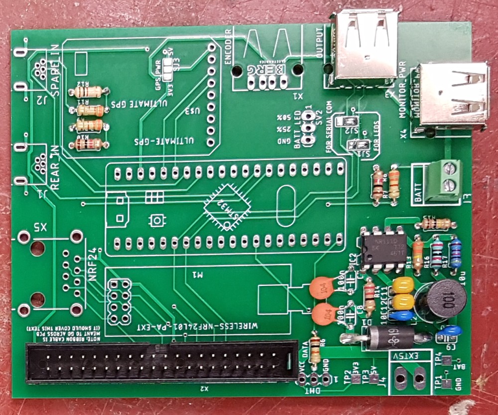
The layout was similarly straight forward to the circuit design. The boards were designed to be taped down in TITAN so there was no need for any mounting bolt holes. Since all the modules were fairly bulky the board was large but sparsely populated except for the voltage regulator corner. The final board was about 100 by 81 mm.
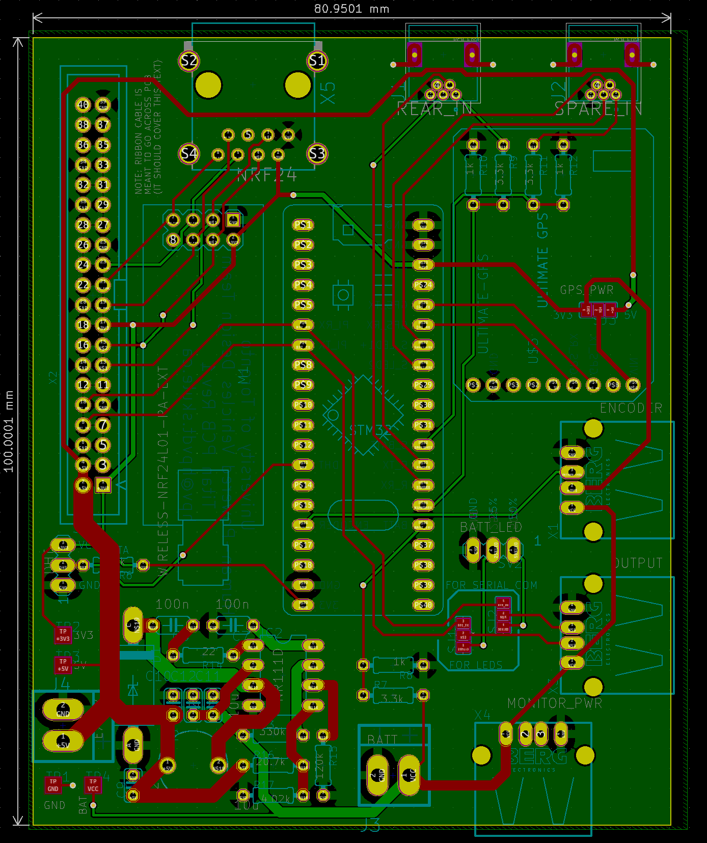
The voltage regulator which occupies the bottom left corner was laid out by my teammate under my supervision. I laid out the rest of the board myself. I added some guiding text for soldering SJ1 and SJ2 to help when we would assemble the system.
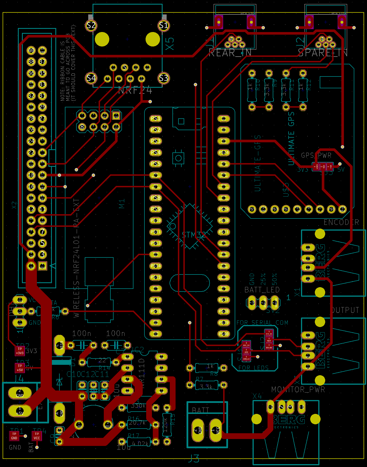
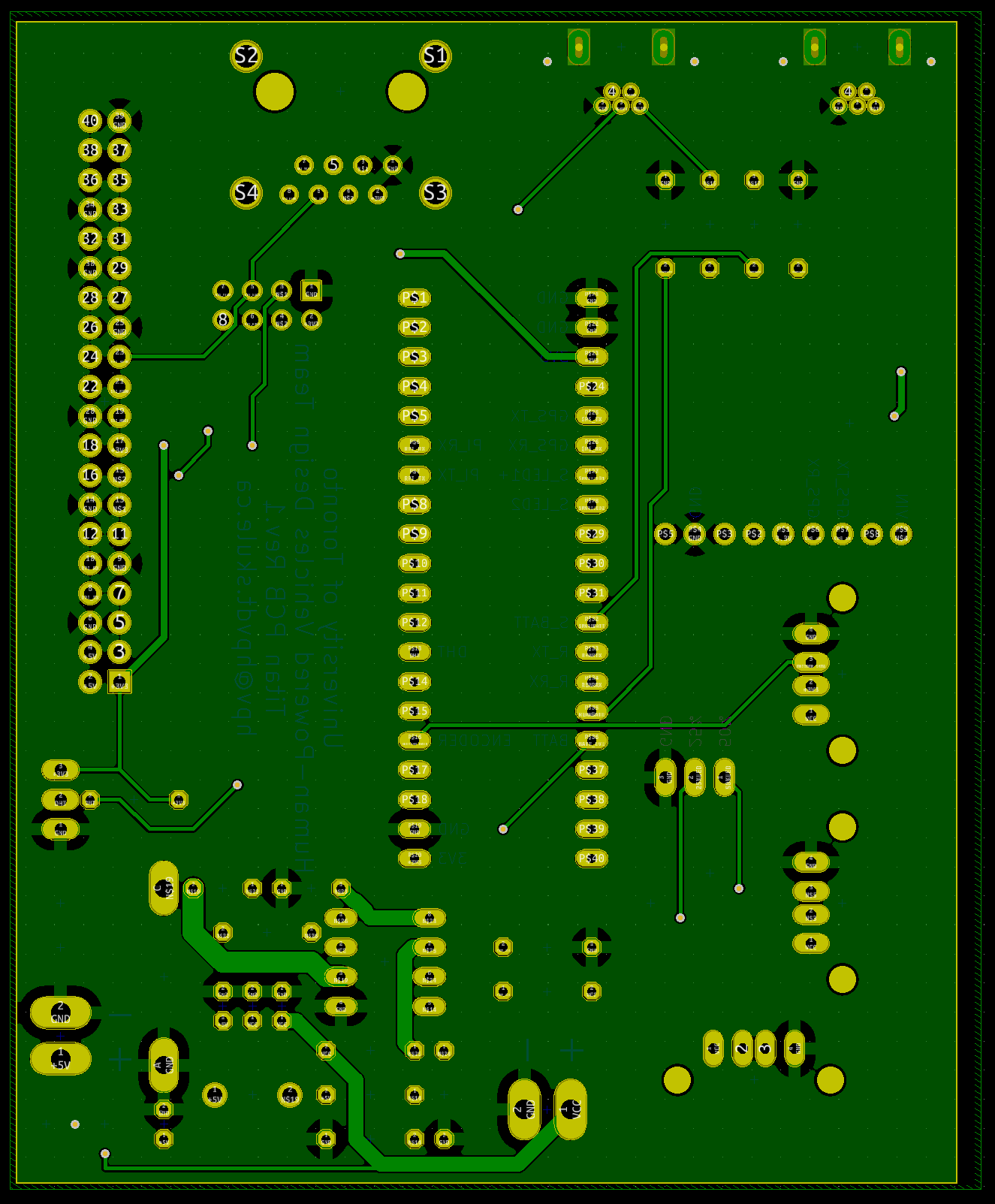
The majority of traces are on the top, the bottom was reserved mostly for a ground plane.
Assembly
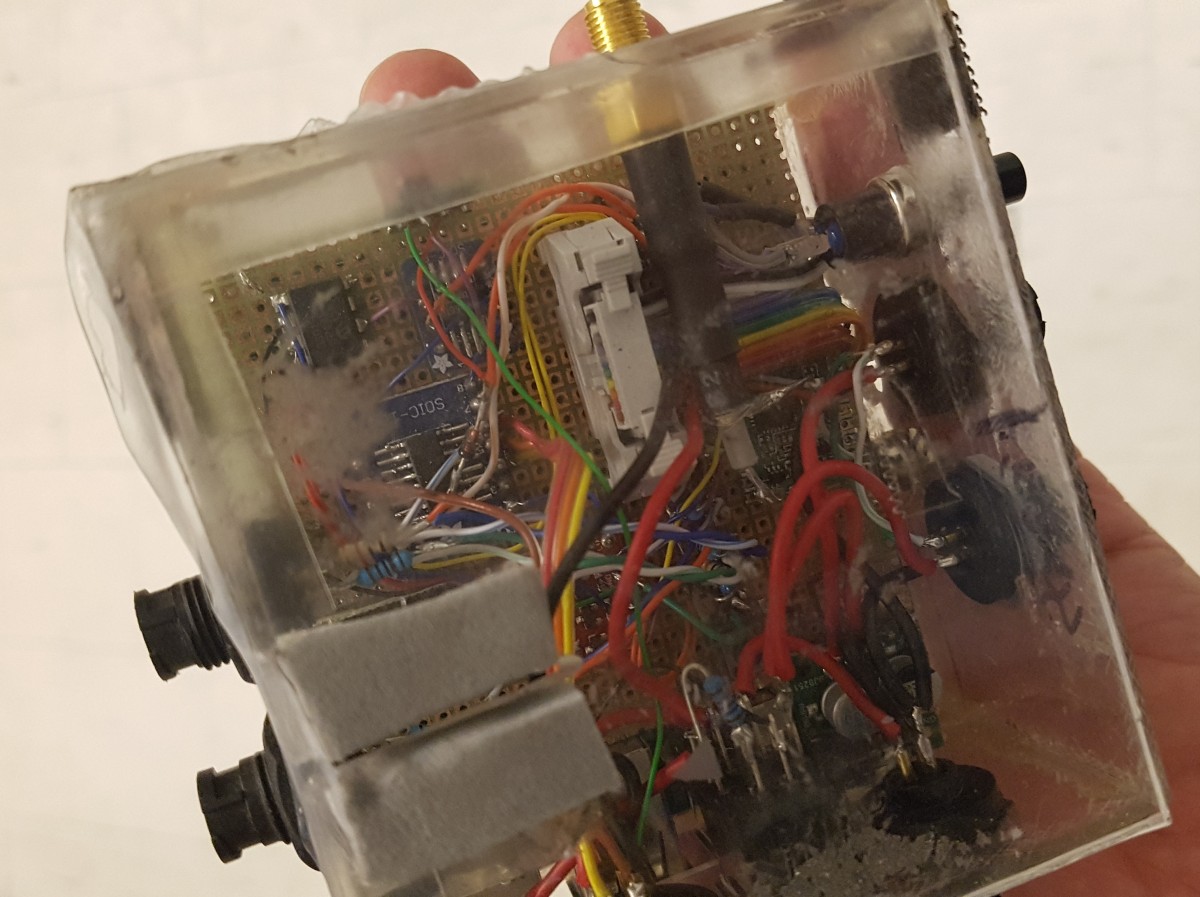
Assembly of the boards was pretty simple thanks to the use of only through-hole components and lots of space between most parts of the board which let me work comfortably.
The main board is obvious in function due to the modules mounted. The GPS had an antenna that came off it for better reception, but I removed it for the photo.
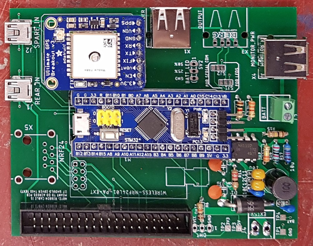
For the rear module I did not bother soldering the connectors for the nRF24 modules because I had recognized at this point that I would be unable to get telemetry to work in time for the competition.
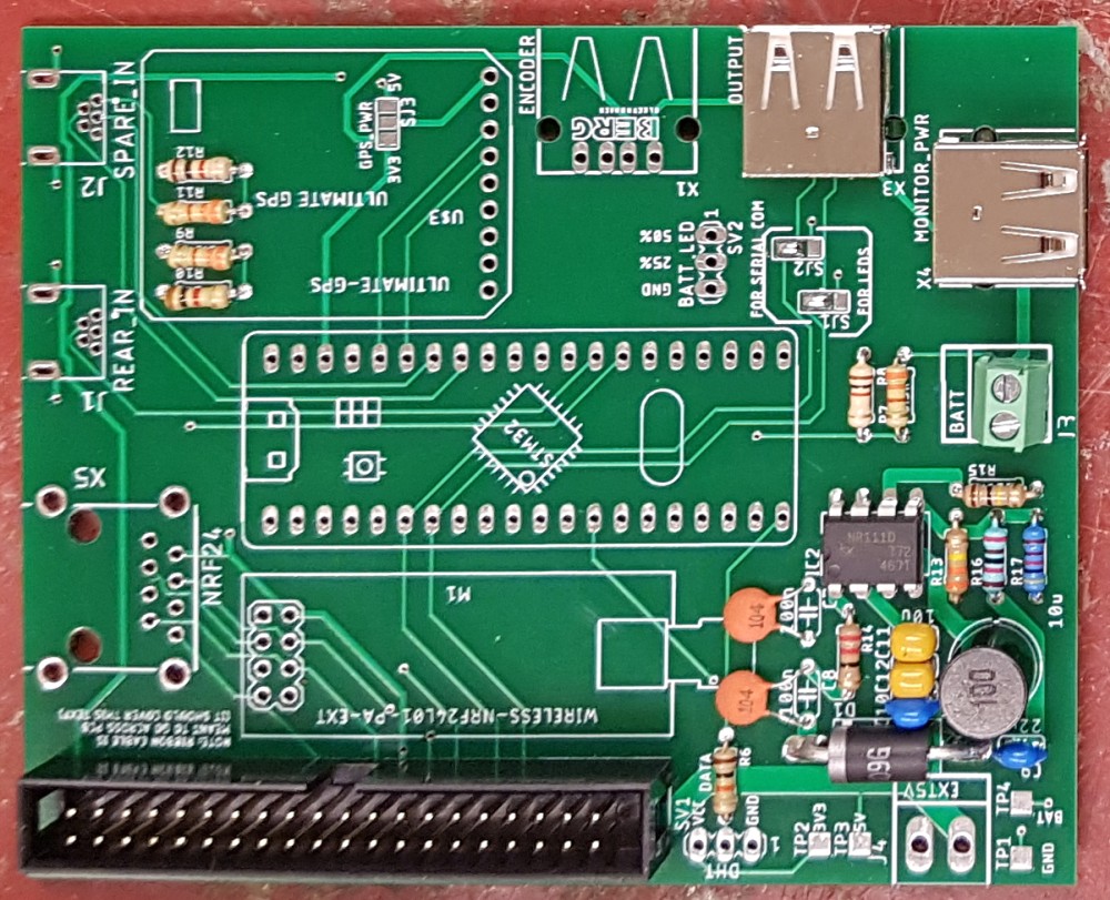
Since I did not solder the nRF24 connectors on the rear board, the only difference between the rear system’s board and the spare/redundant one is the positions of SJ1 and SJ2.
Coding
There were two sets of code needed for TITAN. One set of code for the microcontroller primarily written in C++ using the Arduino IDE and another set to run on the RPis written in Python.
Microcontroller Firmware
The microcontroller firmware was written in C++ using the Arduino IDE. The firmware on it has two main purposes: relay data between the RPis and monitor its sensors. The main loop of code alternates between these duties forever.
Collecting Sensor Data
The microcontroller collects the data it is responsible for in different ways. It collects the level of batteries, and the humidity and temperature in the vehicle periodically every few seconds since these are not rapidly changing quantities. The GPS data is updated as it becomes available from the GPS module. The optical encoder handler is connected to an interrupt so as to not miss any encoder pulses.
For the GPS and DHT module, I made use of freely available libraries for that hardware. This greatly accelerated the development of my code for these sensors since they had already handled the majority of the work. Since it was code used by countless others it was also more reliable than what I probably would have written from scratch.
All the sensors and their implementations were tested unit-wise on their own before I combined them into this firmware.
Battery Monitoring
Of the four data streams I had to prepare, the most challenging was the battery monitoring one. For the GPS and DHT I used their libraries, so it was a trivial matter of calling the right functions. For the encoder I just incremented a counter and converted a period into rotation rate, grade school concepts really.
Monitoring the batteries was more difficult though since this needed some more complex processing and there wasn’t a library I could just drop in. First there was the obvious issue of converting an analog-to-digital (ADC) reading to an actual voltage, since the ADC return an integer between 0 and 4095, with 4095 corresponding to a reading matching the reference voltage supplied (roughly 3.3 V). This conversion would then be compounded by the voltage division for each battery, that would vary slightly across the three dividers due to manufacturing tolerances. This needed me to calibrate the readings to a known voltage and store them on the chip. My final code for this looked something like:
reading = float(analogRead(FBPin));   // Read ADC
reading = reading * divFactor;        // Multiply by resistor division factor to get the actual input
reading = reading / readingToV;       // Divide by constant to convert the ADC steps to actual volts
Knowing the battery’s true voltage wasn’t enough to determine the battery level since the voltage of the battery does not vary linearly with charge level. Each different battery chemistry has its own characteristic discharge curve. The discharge curve of an LiFePO4 battery I used is described here. Note: the batteries referred to in the article use four (4) cells in series, the ones I was using only had three (3) so my voltages were all going to be 3/4 that of what was described there at the same charge level.
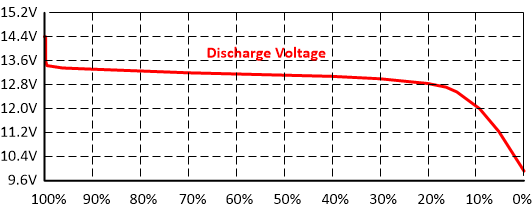
To convert a voltage to a charge level, I would fit the voltage reading to the curve using linear interpolation between a set of key points.
const byte level[] = {100, 99, 90, 70, 40, 30, 20, 17, 14, 9, 0}; // Percentages linked to voltages
const float voltage[] = {10.2, 10.05, 9.975, 9.9, 9.825, 9.75, 9.675, 9.6, 9.375, 9, 7.5}; // Voltages

// Run though set point from top to bottom
for (byte i = 1; i <= 11; i++) {
  if (reading > voltage[i]) {
    // If the reading is in the region
    float temp = 0; // Used in calculations

    // Linear interpolation formula
    temp = (reading - voltage[i]) * float(level[i - 1] - level[i]);
    temp /= float(voltage[i - 1] - voltage[i]);
    temp += level[i];

    reading = temp; // Stores the result in the reading variable
    break;
  }
}
reading = constrain(reading, 0, 100); // Constrain it to reasonable values

/* Other code */

return (reading);
Communication with RPis
Communication with the RPis was handled over a dedicated serial line for each. The general flow to communication is the RPi sending a message to the STM32, and then the STM32 responds accordingly. The STM32 never initiates an exchange! The structure of the message received by the STM32 followed this format:
1 character - Message type (capital letters are for sending data, lowercase for requesting data)
1 character - Data length, n (only if the RPi is sending data)
n bytes - Data to STM32 (if the RPi is sending data)
If the RPi is requesting data for itself, it will simply send a lowercase letter for that field, e.g. “s” for speed. If it has data it wants to impart on the STM32 (to pass on to the other RPi), like the ANT+ data, it will start with a capital and be followed by the data length and data itself. E.g. “D!55” would be used to set the right cadence (D) as “55” which is 2 characters long ("!" has the ASCII code of 33, but I add/subtract 31 to the lengths to keep length characters printable since the first printable character is space, " “, at 32).
When the STM32 is responding with data to a request, it replies with just the data length and data itself (no leading message type character).
The reason I used a data length character as part of messages, rather than a fixed length or delimiting character to communicate message length is because it allows for greater flexibility than a fixed length, and it doesn’t risk a delimiting character randomly occurring in exchanged data, misleading the RPi or STM32.
Raspberry Pi Code
Unlike the STM32, the code for the RPis was written entirely in Python. I had a basis to work off of given the work done for Eta Prime, however I reworked much if it for various reasons. The main reasons for this refactoring were:
- Different hardware configuration (Eta Prime did not have a microcontroller to help with data collection)
- Different system needs, namely to share data across multiple RPis
- Migrating code between Python 2 and 3
Camera Feed
To put the camera feed onscreen and have it recorded was actually pretty simple and accomplished in less than a dozen lines of code thanks to the work of the Raspberry Pi Foundation.
camera = picamera.PiCamera()
camera.resolution = (self.VIDEO_WIDTH, self.VIDEO_HEIGHT)
camera.framerate = self.FRAMERATE
camera.brightness = self.BRIGHTNESS
self.camera = camera
self.camera.start_preview()

# Setup recording file
self.RECORDING = recording # Record if recording or not
if recording:
    video_title = "{}.h264".format(time.strftime('%y%m%d-%H:%M:%S', time.localtime()))
    self.video_title = '/home/pi/Videos/recording-' + video_title
    self.camera.start_recording(self.video_title)
This code would put the video feed over the entire screen as a “preview”, and start recording it to a fill if desired. The settings we could manage were a stable 720p HD video, at 60 frames per second.
Overlay
The overlay code needed a decent amount of rework, since a core library it depended on was written in Python 2. The library was specifically used to create the overlay image with all the data for the riders. Initially I wanted to replace it with something similar but capable of running in Python 3, however I was unable to find a suitable alternative at the time. So instead I opted to run the entire system in Python 2 instead.
Once I had the system working, I could produce a text overlay pretty simply. I would just place text boxes around the screen as I wanted and fill them with the text I desired with some basic properties defined. These text boxes were actually drawn on a temporary canvas/image, “img”, initially.
font = ImageFont.truetype("../res/consola.ttf", size)
draw = ImageDraw.Draw(self.img)
draw.text(position, text, color, font)
Once I was done drawing all the text I wanted on the canvas I would update the overlay with this canvas simply with:
self.overlay.update(self.img.tobytes())
Communication with STM32
Communication protocol with the STM32 was outlined briefly in the STM32’s section on this. The only thing worth mentioning on the RPi side of things is that the RPi’s block (wait) the program until a response is received following a request. This is why the STM32 doesn’t need to specify what its response is for, the RPi already knows.
ANT+
ANT+ was where a sizable chunk of my efforts went into. I found the aptly named “python-ant” library online and it supported operation on the RPi. Not only that but it had examples for a heart rate monitor and power pedal, the exact two devices I needed to operate!
I started by starting the network and then connecting to the devices using the USB dongle. Most of this was copied directly from the examples provided with the code.
from ant.core import driver
from ant.core.node import Node, Network, ChannelID
from ant.core.constants import NETWORK_KEY_ANT_PLUS, NETWORK_NUMBER_PUBLIC
from ant.plus.power import *
from ant.plus.heartrate import *

device = driver.USB2Driver(log=None, debug=False, idProduct=0x1008)
antnode = Node(device)
antnode.start()
network = Network(key=NETWORK_KEY_ANT_PLUS, name='N:ANT+')
antnode.setNetworkKey(NETWORK_NUMBER_PUBLIC, network)

...

frontPWR.open(frontPedals, ANT_TIMEOUT)
print("Connecting front pedals")

frontHRM.open(frontHRM, ANT_TIMEOUT)
print("Connecting front HRM")
Working with these examples I looked at how they worked and gained a bit of understanding about Python callbacks since they are an integral part of how this library worked. Eventually I prepared my own, so that when a heart rate or power value was registered, the system would share it immediately with the rest of TITAN.
# Functions for broadcasting data
def front_power_data(eventCount, pedalDiff, pedalPowerRatio, cadence, accumPower, instantPower):
    microController.sendData('E', str(instantPower))
    microController.sendData('C', str(cadence))
def front_heartrate_data(computed_heartrate, event_time_ms, rr_interval_ms):
    microController.sendData('A', str(computed_heartrate))

...

frontHRM = HeartRate(antnode, network, callbacks = {'onDevicePaired': hr_device_found, 'onHeartRateData': front_heartrate_data})
frontPWR = BicyclePower(antnode, network, callbacks = {'onDevicePaired': power_device_found, 'onPowerData': front_power_data})
All this was not peachy though. I had to make some adjustments to the library. These were probably due to me running it in Python 2 rather than 3, although it has been a few years so I forget the exact issues. Once I had the code to just gather a few devices of interest I developed code to run this as part of the TITAN system. For example I prepared a function to ensure that all devices were connected and alerting the riders if any failed to connect if they didn’t.
Testing the code for these was some fun. To test the heart rate monitor I wore it and would either hold my breath or begin hyperventilating to observe a change. As for the power pedals I actually had an exercise bike I would pedal on for testing. We now have additional ANT USB dongles I could use to simulate the output of a device but I feel that it’ll ruin much of the fun involved in the process.
Radio Communication
I initially wanted to get some telemetry working with the nRF24 modules I found, I even had some radio libraries ready, however I didn’t have the time to properly develop or test any code related to this so it was never implemented.
Assembly into TITAN
Assembling the system into TITAN was not as easy as we had anticipated, but still successful.
There was significantly more wiring involved in this than either of my previous projects for the team, much of this was necessitated by the cameras and displays not being placed near one another. Luckily most of the wiring was able to be routed within the hollow frame/roll-cage, with the ribbon cables for cameras run along them.
Although tedious, routing the cables wasn’t the most problematic. We had issues fitting the TITAN boards nicely around the vehicle given their size and the ribbon cable between them and their RPis. Each display entailed three separate, moderately-large boards (RPi, my board, display driver) for a total of nine in TITAN.
My teammate and I had some issues setting up the optical encoder on the rear wheel. Initially we wanted to use a laser based encoder that would be interrupted by the passing spokes of the brake disk. However after some testing it was found that the laser would inevitably lose its alignment with the optical sensor. Our solution was to replace the laser with a red LED since the LED’s light was much less directional than the laser and thus could tolerate more misalignment.
Outcome
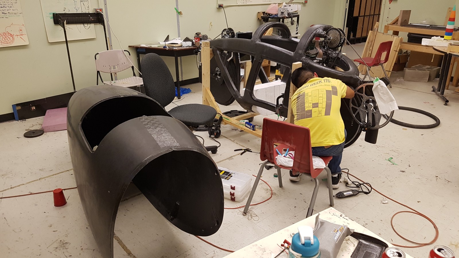
Soon after we installed the system, TITAN went off to the competition (the figure of my teammate installing electronics was taken September 1st, 2019 - mere days before the team set off to compete). This left little time for me to test the system in situ.
I was not able to join the team going to compete so I was unable to provide technical support there if it began to misbehave. I did however prepare a manual with some brief trouble shooting guides for those that did go. Unfortunately I did not anticipate some of the issues they faced with the program, and instead of addressing them and fixing my system, they elected to use the system from Eta Prime instead.
When they returned I collected their feedback and identified several suggestions for the system going forward:
- One RPi/board pair resulted in a boot loop
- Likely caused by a poor voltage regulator
- The camera feed would flash black periodically, seemingly cutting out.
- Initially suspected to be the result of loose connections in a vibrating environment
- This was later found to be caused by the overlay updating process.
- The rear facing camera was useless
- Perhaps display historical data trends on the rear display instead
- A front-facing feed?
- Add dedicated power buttons for RPis instead of relying on connecting and disconnecting batteries
- Start the camera feed on boot, not debug messages
- I should consider using a direct camera-screen setup for the back-up video feed
- Reduces number of potential failure point
- Simplifies circuit
- Cheaper?