Laser-Eyed Raccoons
Table of Contents
Overview
I wanted to make some gifts for my friends that hosted me when I was visiting Paris, something with a personal touch so I set about trying to make some circuit boards for them, ideally at least one that was interactive, so I decided to make a raccoon to send them a bit of the urban life we have here Canada. This would also be great for me to gift some of my family that aren’t super technical, since it’s a little flashy gizmo that’s pretty easy to use.
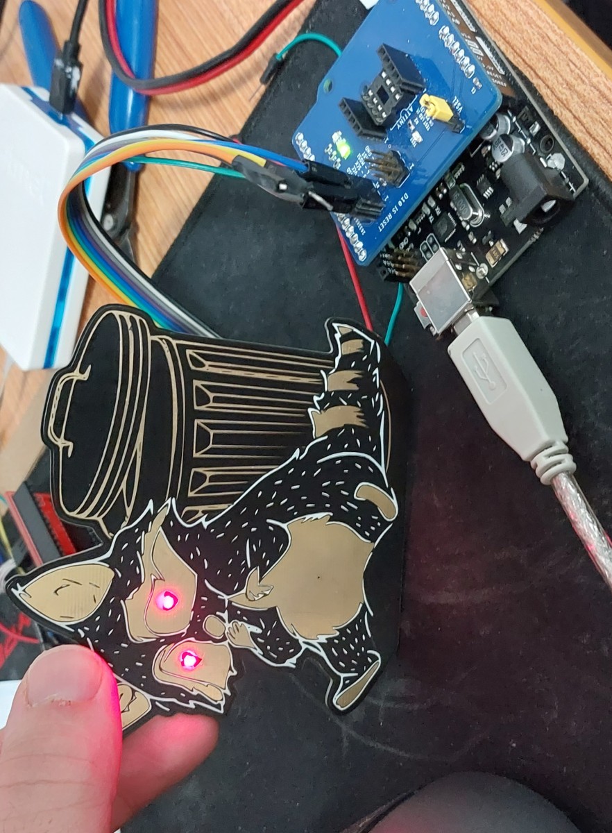
The board was to resemble a raccoon and when you touch its belly its eyes would light up. Ideally it would run off a battery for a over a year.
This was my first time making a functional board where aesthetics were of paramount concern. Also it was my first time working to try and get ultra low power consumption, excluding my flirtation with it while working on my entry fob project.
Overall I am very satisfied with the way these came out, with the stands they’re great decorations. I even had a friend offer to pay for one so I finally made some money with my hobby!

Requirements
- Board needed to look like a raccoon
- Eyes need to illuminate when a finger is sensed on the belly
- Needs to run for several months off a single battery
Objectives
- Eyes to respond within a couple of seconds
- Have the system run for over a year off a single battery
Takeaways
Making nice circuit boards takes a bit of research to decipher the process, but is relatively simple to do once you decide on a method. I look forward to trying this again!
It takes some effort to snuff out the last remaining peripherals that are using power to really bring a microcontroller down to a level where it is sipping power (sub 5 uA!!) and it leads to some obvious trade-offs in terms of system responsiveness. However even minor changes such as reducing clock rates or just driving unused pins to ground can have a noticeable impact on power draw, without impacting performance.
Detailed Report
As part of the gifts I wanted to send back to my friends that hosted me in Paris, I wanted to make things with a personal touch, ideally related to my electronics projects which fascinated them. So I set about trying to make some circuit boards for them. I made a few that were purely aesthetic, namely for their business: a virtual reality cafe, so the circuit aesthetics meshed well - but I wanted to make at least one that was interactive, so I decided to make a raccoon to send them a bit of the urban life we have here Canada.
I knew that the circuit was going to be simple hardware-wise and that the effort was going to be focused on the art and the capacitive sensing system code.
Developing Firmware
Unlike most of my projects, I had basically completed developing the firmware well in advance of the actual hardware being designed fully. For testing I had little more than an ATtiny85 on a bread board connected to the LED and a jumper wire used for touch sensing, and the programming and power connections.
Capacitive Touch Sensing Code
I started with getting capacitive sensing to work correctly. This way I would know it worked before I potentially disable it in my power reduction efforts. For it I made use of the TinyTouchLib which uses some hardware non-idealities related to the Analog to Digital Converter to detect changes in capacitance of a line. To use it in code was pretty simple, first there would be a set up called:
tinytouch_init();
Then in my main code loop I would use the following to light up the eyes when a touch is detected (not a “hold”).
if (tinytouch_sense() == tt_push) {
  digitalWrite(eyesPin, HIGH);
  delay(eyesOnTime);
  digitalWrite(eyesPin, LOW);
}
Other than these blocks of code, I only had to tweak the library to match my pin allocations and tune the sensitivity of the system to the changes in capacitance it was experiencing in my setup.
Power Saving Code
Once I had the capacitive touch sensing code working reliable I began to work on reducing the power draw of the system. I first began by trying to have the system idle using delay() for ten seconds between checks. I hooked up my multi-meter to monitor the power supplied to the system and began to monitor.
For reference, I planned to use CR2032 batteries, which provide 3 V with a capacity of around 340 mAh.
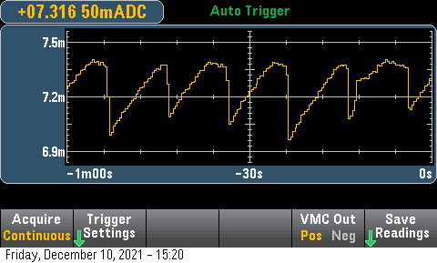
With the ATtiny85 running at its default 8 MHz internal clock at 5 V, the current draw averaged about 7.2 mA. This would kill a CR2032 in just under 48 hours. Although not super relevant to the project, it was odd to see a noticeable saw-tooth pattern to to current draw as it steadily increased during the delay() call. I wonder why that was.
With this (horrible) baseline I went about doing two simple things. First I lowered my supply voltage to match the expected 3 V it would have in system (instead of 5 V), and then lowered the clock of the microcontroller from 8 MHz to 1 MHz. These corresponded to a 33% and 75% reduction in power draw, down to about 1.4 mA with both in effect.
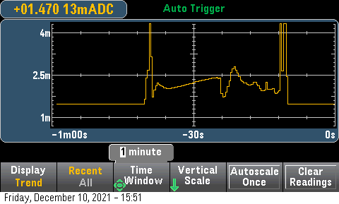
Then I began to change my code to save power. First I started by following the recommendation in the datasheet (Section 7.4.6) to drive unused pins rather then leaving them floating. If left floating they will hover around half the supplied voltage and thus constantly toggle the digital input buffers between states, drawing power. This is shown in the plot below, where the unused pins are driven low for the leftmost (oldest) section and right most, but left to hover in the middle. This saved me roughly 1 mA!
Idling at about 1.4 mA of draw, meant that the system would last about 10 days. Still far off the several months I needed, let alone the year I wanted. I knew the ATtiny could do better since they advertised a sleep current of only 1.8 uA at 1 MHz and 1.8 V. So I started looking into how to properly disable peripherals and put the microcontroller into sleep modes, rather than just using delay().
Power Management Library
Using the avr/power.h library helped me disable power to peripherals that I wasn’t using to save power, by using __power_all_disable(); and __power_all_enable();. I also wrote to some of the power management registers myself where it seemed the the power library didn’t have an effect.
// Reduce power use by disabling peripherals
ACSR |= _BV(ACD); // Disable analog comparator
DIDR0 = _BV(AIN1D) | _BV(AIN0D); // Disable digital input buffers on analog pins (we don't need digital in)
PRR = _BV(PRTIM1) | _BV(PRTIM0) | _BV(PRUSI) | _BV(PRADC); // Timers, universal serial interface, ADC
These lines of code shaved off a several hundred uA, bringing the system down to about 800 uA.
Sleep Library
The final frontier of power reduction was getting the microcontroller to sleep properly. In deep sleep basically everything inside the ATtiny is shutoff with the exception of the watchdog timer and some of the input systems so that the microcontroller can be brought back into action. Since I wanted the raccoon to check periodically, every couple of seconds or so for a touch event I used the watch dog timer to pull the microcontroller out of the deepest sleep.
To put the ATtiny into sleep I used the avr/sleep.h library. I would simply set the sleep mode in my setup with just set_sleep_mode(SLEEP_MODE_PWR_DOWN); so the ATtiny would go into the deepest of sleep when prompted. To put the microcontroller into sleep mode, I just needed to call sleep_mode(), and then to disable sleep mode after being “awoken” by the watch dog timer so it could check the capacitance, sleep_disable().
Setting up the watchdog only took a few lines, done in the required sequence outlined in the data sheet. The interrupt it triggers is empty as it only serves to pull the ATtiny out of sleep, sleep_disable() is called in the main loop after the sleep_mode() line.
MCUSR &= ~_BV(WDRF); // Reset WDT

// Start timed sequence to set
WDTCR |= _BV(WDCE) | _BV(WDE);

// Set new watchdog timeout value
WDTCR = _BV(WDCE) | _BV(WDP2) | _BV(WDP1) | _BV(WDP0); // 2 seconds

//  WDTCR = _BV(WDCE) | _BV(WDP3) | _BV(WDP0); // 8 seconds
//  WDTCR = _BV(WDCE) | _BV(WDP2) | _BV(WDP1); // 1 second
//  WDTCR = _BV(WDCE) | _BV(WDP2) | _BV(WDP0); // 0.5 seconds

WDTCR |= _BV(WDIE);
Disabling ADC
Regardless of putting the ATtiny into the deepest of sleep where all peripherals were shut off, I still needed to manually disable the ADC using its control register, in addition to calling __power_all_disable() before going to sleep, otherwise it runs through sleep. Without specifically disabling it, the sleep draw would be 230 uA higher due to the continued ADC operation. This took me quite a while to figure out. The reason for this I found out was that the ADC is kept on through sleep modes since a way to minimize noise on the ADC’s readings is to have them occur while the rest of the microcontroller is in sleep, hence why the ADC needs to be specifically disabled. This is covered in data sheet as “ADC Noise Canceler”, section 17.7.
Bringing it all Together
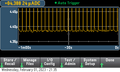
With sleep and the power reduction code implemented, the idle current draw of the system was brought down to… 4.4 uA! (This draw varied slightly board to board, and with the voltage supplied, but never exceeded 5 uA.) At this draw it will last about 3000 days, or roughly eight years on a single CR2032. Granted it will likely be much lower because it consumes several mA when running the capacitance check for a few milliseconds each couple of seconds, and then several mA for a few seconds when a touch is detected. Even so I don’t think it would be unreasonable to expect these to operate for over a year under normal use (lighting up a couple of times a day).
The sleep portion of my code followed this snippet. The delay at the end before my capacitive sensing code can probably be reduced.
// Sleep cycle
ADCSRA &= ~(_BV(ADEN)); // Disable ADC
__power_all_disable();
sleep_mode();
sleep_disable();
__power_all_enable();
ADCSRA |= _BV(ADEN); // Enable ADC
delay(10); // Needed for ADC warmup/stabilization
Circuit Design
The circuit design was pretty simple, I basically transcribed the working configuration I had for my hardware during the firmware development process, making minor modifications to include a battery for power and a programming header.

Board Design
The board design was pretty unique for me since I had to accommodate the custom artwork, something I haven’t had to do before. First I had to prepare it and then I had to work my circuit layout around it.
Preparing the Artwork
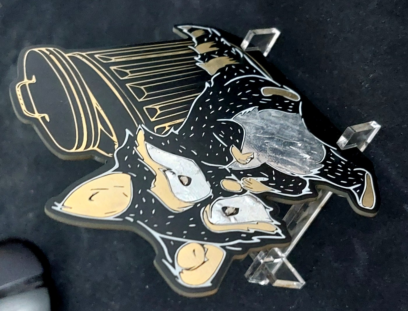
I am not an artist, luckily I was able to enlist the help of my sister to make me the artwork I was looking for. I gave her these requirements:
- Cannot exceed 100 mm x 100 mm
- Limited to the palette available for my PCBs, based on the PCB production limitations.
- Black (solder mask over no copper)
- Gold (plated copper)
- Silver (solder on exposed copper/gold)
- White (silkscreen)
- Lighter black (copper fill under solder mask)
- The tummy needed to be filled with copper.
- Need a specified outline
With these she produced the following image for me to use. Originally a vector image then I converted it to a bit-map.

The reason I originally had her prepare it as a vector image was to make use of Gerbolyze for putting the art in place. However the problem with Gerbolyze I found was that it is meant for functional art, which means it will maintain a clearance around any functional parts of the system, not acceptable for me since I wanted the raccoon’s stomach to be connected as a capacitive sensing pad.
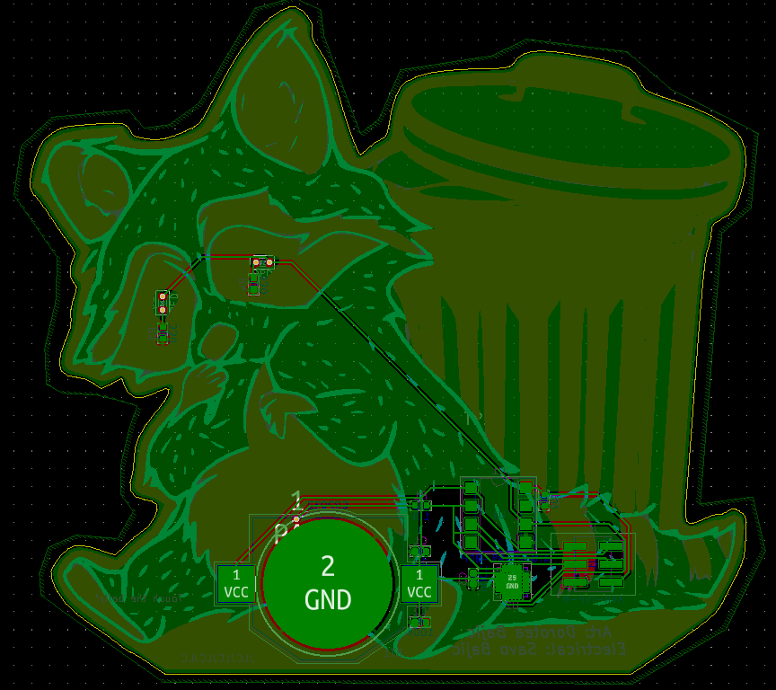
So I moved to using KiCad’s built-in bit-map to component utility. This allowed me to convert individual PNG files into the polygons and use them in any layer, e.g. “top silk screen” or “bottom solder mask”. To use it I broke down the art into the layers each feature needed to be on.


With them all converted, I got the following render of the board. Looked sweet! Note that in KiCad I couldn’t selectively set the pads that would be coated in solder so they would render silver alongside the gold, hence why it is all gold.

Look, it has a little belly button!
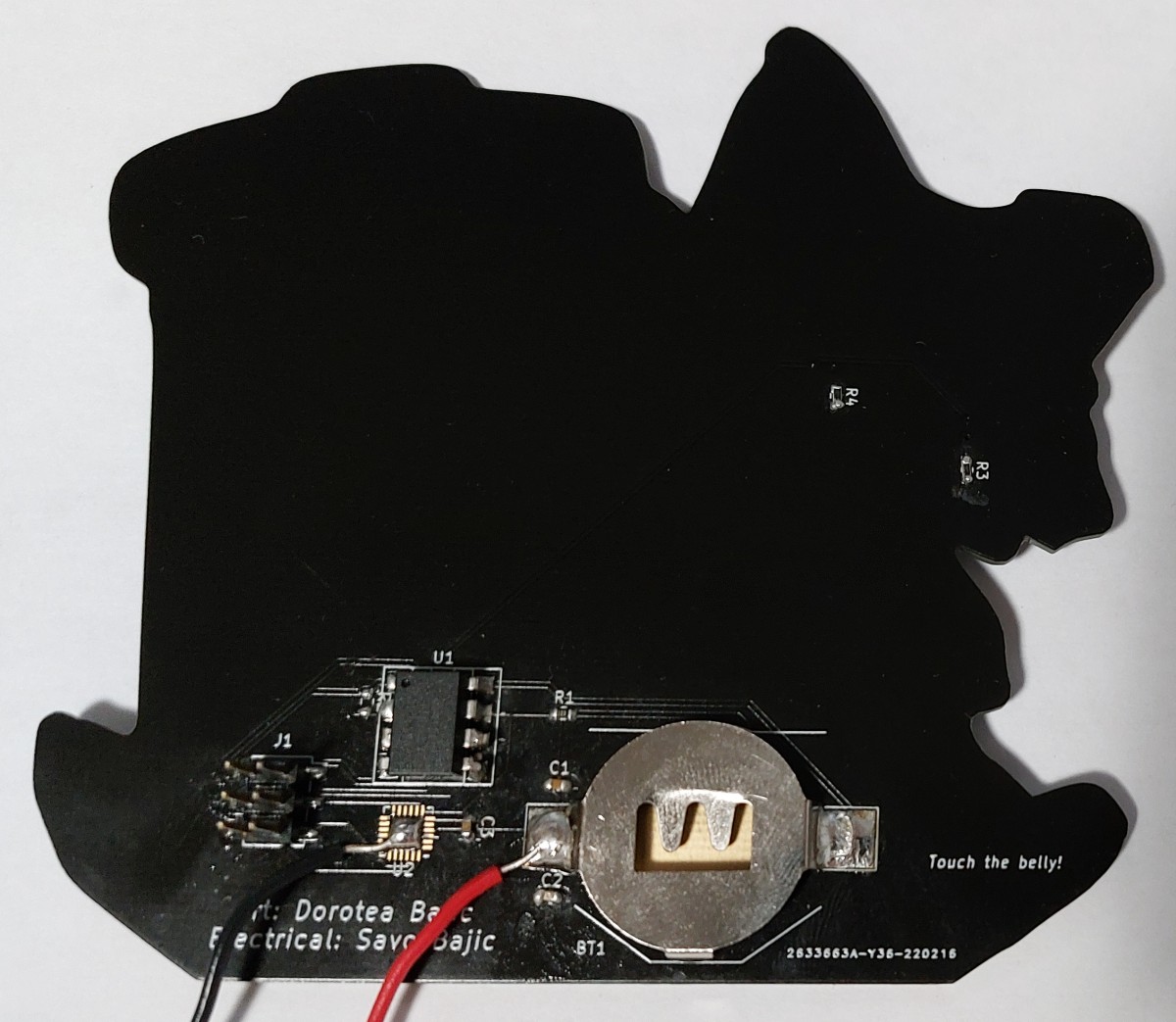
Actual PCB Layout
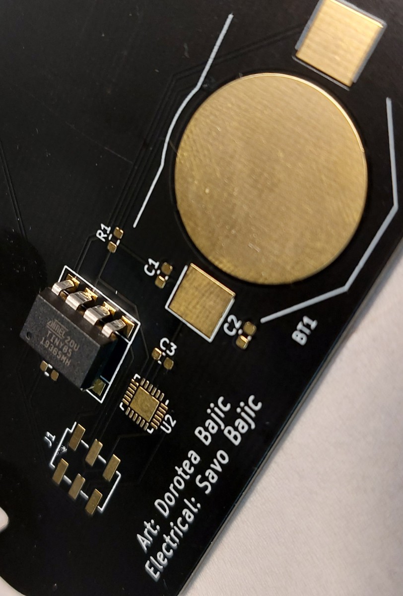
With the components made for all the different art layers, I simply placed them properly relative to one another to achieve the design.

Since I wanted the art undisturbed (except for the eye LEDs), I had to try my best to do all the routing on the back that I could. I was successful in this thanks to some very windy traces; vias are used to deliver power to the eyes with them emerging at the LED pads where the LED will cover them.
Assembling the Boards
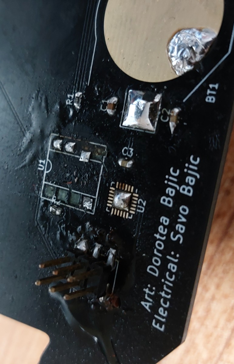
This was the first time I had ordered gold-plated boards (ENIG process), and damn were they more expensive, a scratch over triple what I usually pay per board. I think the cost was worth it though when I saw and held them.

Assembling the boards was pretty basic, I just hand-soldered everything in place. In order to bring the DIP8 package for the ATtiny85’s close to the board I cut the leads a bit shorter with side cutters.
A minor side note, but I really like the look of parts on these gold-plated boards before soldering. Shame it’s so pricey.
Plating the Belly and Eyes
Since we wanted the belly and eyes to be silver I had to hand coat them with solder. This was easier than expected although the belly cooled quickly so the soldering iron would leave “ripples” of solder as it moved across the surface, like a paint brush.

I found that if I applied hot air as I moved the iron I could prevent the rapid cooling and result in a smoother belly plating. The effect is quite similar to Hot Air Solder Leveling (HASL) typically done for cheaper boards.
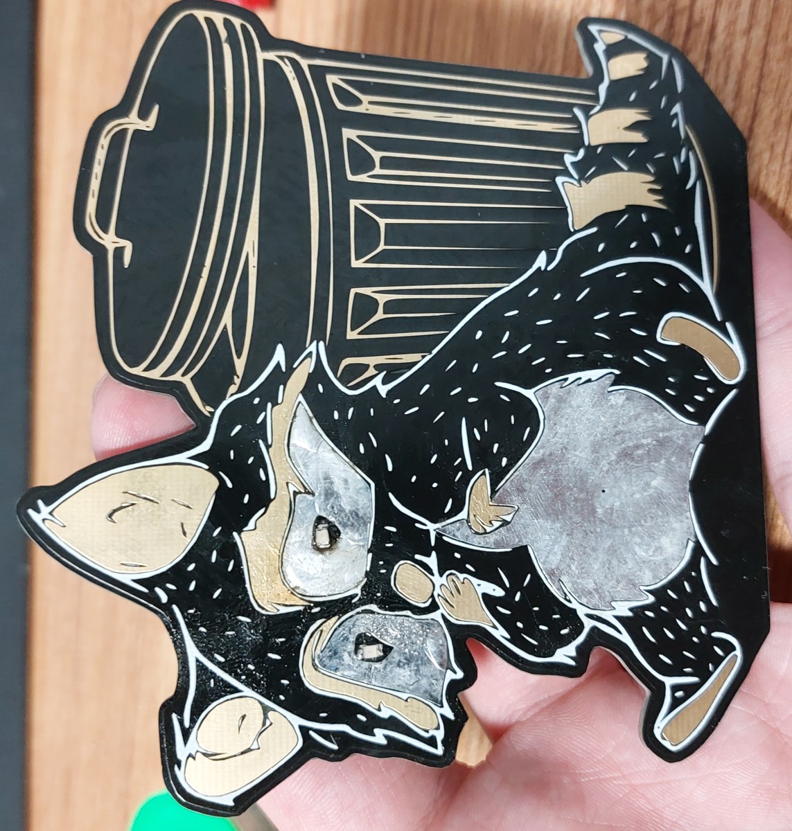
In the end I ended up primarily just hand soldering all the boards and not bothering with the hot air since I felt that the differences were negligible to most and the “brushstrokes” made it feel a bit more artsy to me.
Testing the Assembled Boards
Once I had assembled one board I began to test it to make sure there weren’t any issues stemming from my assembly nor the design itself. The initial power applying test passed, current was drawn at about 10 mA when 5 V were applied, which was what I expected for a blank ATtiny85, so no obvious shorts or non-functional components.
Programming Issues
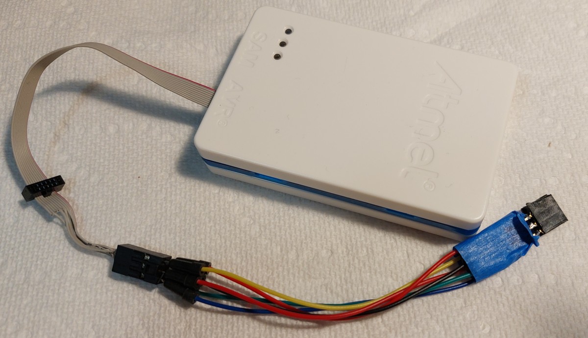
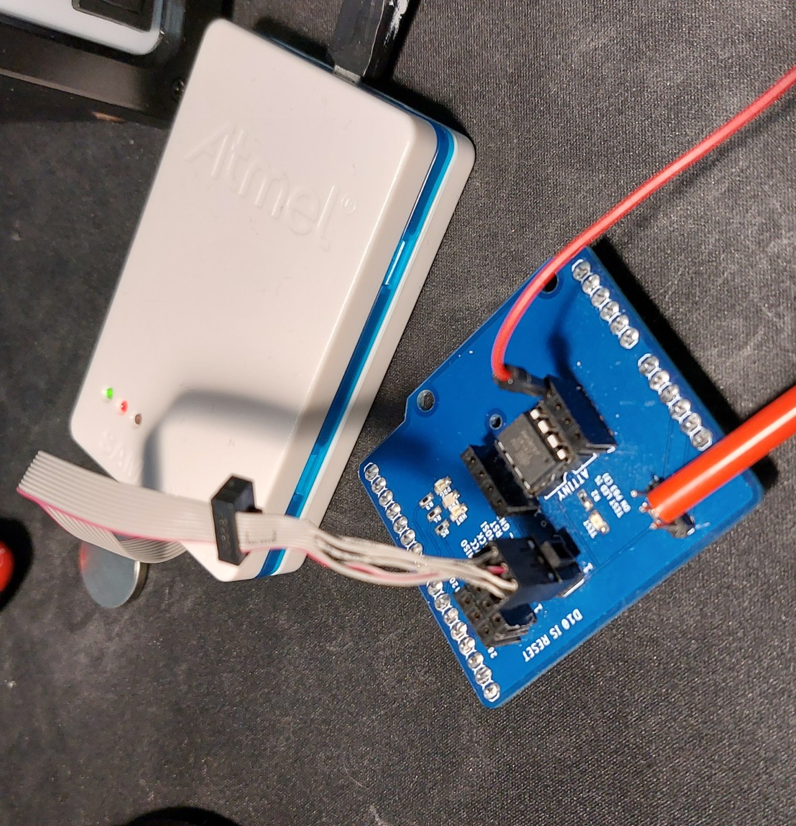
Since the board passed the basic power-on test I went to try and upload some basic code to the ATtiny85 using my ATMEL-ICE in system programmer. I plugged it into the header but failed to get it to work or even recognize that it was connected to a system, it didn’t even tell me that the target was powered which it certainly was!
After some poking around I decided to double check the connections, since they tend to be the culprit of most electrical issues. Sure enough, it was! It turns out that my connections were prepared correctly on the schematic, so each signal was on the correctly numbered pin - however, I had accidentally selected a pin-socket, not a pin-header for the footprint so the pins were mirrored.
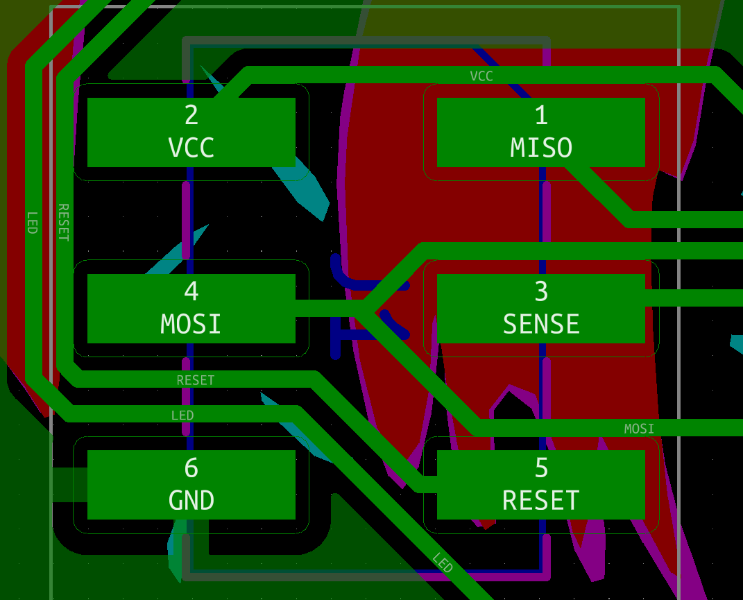
Below is the proper layout, note how number-for-number they match properly. It is a good thing that I was using an isolated programmer and not supplying power on these mirrored connections before I figured this out, otherwise I would have likely fried the ATtiny chip. (I got my ATMEL-ICE only a couple of weeks before I started this project.)
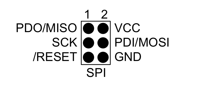
This was quite annoying since I needed some intermediate connectors between the programmer and the board to route the signals properly. If this was a through-hole header I could have simply put the header on the opposite side and that would have corrected this issue too.
Initially I used some M-F ribbon cable jumpers to re-route the signals between the programmer header of my ATMEL-ICE and the raccoon. This seemed to work, but only partially. The board/chip would be recognized, but any attempt to write any code to it would result in failure since the ATtiny would fail to respond with the correct device signature. I found the cause to be the excessive length of my programming wiring (roughly a combined 35 cm from end to end) from some forums online. Since I did not have shorter M-F jumpers to use with my proper programmer, I opted to use my ol’ reliable Arduino as an ISP system which would have a shorter wire length, which worked!
Even though I could continue using the Arduino as an ISP, I wanted to use my programmer since it was safer and would also make it easier for me to ensure that the power draw was what I expected since the board could not potentially draw power from it instead of from the monitored power supply. Since I didn’t have some shorter M-F jumpers I made a F-F adapter using two 2x3 pin-sockets soldered end-to-end which would then allow me to use my short M-M jumpers to mirror the signals between board and programmer. This solution worked and I kept it for the remainder of my development process.
Power Draw Issues
Once I was able to reliably upload code to the raccoon boards I went ahead to check the power draw of the boards met what I was expecting, roughly 5 uA at 3 V, when in deep sleep. After uploading my previously prepared code to the microcontroller, I started monitoring the power draw and… it was off the charts! The maximum draw was supposed to be roughly 10 mA when the LEDs were on, but this board was drawing over 20 mA with them off!
This honestly scared me, since this was way above what I expected. However I tested it and the system worked, reacting to my finger as expected, just gobbling up way more power than expected. The power draw seemed to vary over time, rising and lowering to the tune of several mA, which struck me as odd since its behaviour was constant. So I left it to run for a while after maybe 15 minutes unsupervised, I saw that that the power draw had been steadily rising and had reached 160 mA at 3 V! This shocked me so I reached for the board to see how the ATtiny was holding up, since with that much current it was likely going to be warm to the touch, but it wasn’t, and that confused me even more.
I turned off the power and de-soldered the chip from the board, so I could program and monitor it on its own to see what the issue was since I believed it to likely be a fried chip.
As soon as I had powered on the ATtiny85 on its own, on this programming board, the power draw was exactly what I had expected, roughly 5 uA! I was flabbergasted. So I slowly assembled a new raccoon using this chip, applying power between each component installed to see which caused this massive leakage. At the end of it the assembled board worked fine, and was still only drawing the power I expected. So I had a proper, finished board but no answer for why the original board failed so spectacularly.
After some discussion with my friends I learned that the current leakage was likely caused by the excessive flux remnants on the board from my rework to make the solder joints nicer that I had not bothered to clean off properly before testing. I accidentally over heated the pads as I removed the microcontroller so I cannot reassemble the board and clean it to check, however since no other board has had this issue since I began to clean them properly before testing, I think it that I’ve solved the issue.
Final Touches
With my first (two) boards completed I was ready to begin making the rest of the raccoons to match. However I had to tweak two parts of the code. First was the the capacitive sensing thresholds: I needed to accommodate the pads of the board compared to the jumper wire I used in initial testing which took some trial and error but eventually I arrived at some proper values. Secondly I needed to decide on a check frequency for the capacitive portion.
Adjusting Check Frequency
Adjusting the check frequency is a direct compromise between responsiveness and power consumption. I wanted the system to last at least a year on a single battery so I needed to keep the nominal current draw pretty low. To calculate the nominal current draw I added the average sleep current to the average active current multiplied by the portion of time the ATtiny would be active. Note that the power expended when the LEDs are on is omitted since I am assuming they will only be on for an insignificant enough of a portion of the device’s time. The rough formula for this would be:
$$ I_{Average} = I_{Sleep} + (I_{Active} * P_{Active}) $$I started with a baseline of checking every second. So \(I_{Sleep}\) was roughly 4.5 uA, \(I_{Active}\) was 7.2 mA, with a \(P_{Active}\) of 0.01 (10 ms per second), which yielded an average current of 76.5 uA. At this current draw the CR2032 cell’s 340 mAh would be expended in 185 days, or half a year. So I simply halved the check frequency to once every other second to extend this to approximately a year.
Mass Assembly
I assembled all the boards as I had (save for the one I accidentally ruined when removing the the ATtiny85). I’ve handed them all out except for the ruined board and one I kept for myself on my desk.
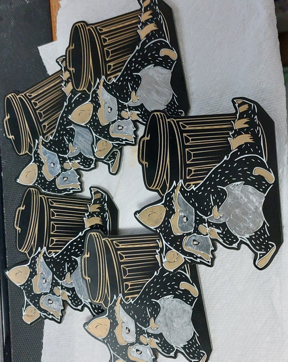
A group of raccoons is called a nursery or a gaze. I however feel that gang is more fitting for the little thieves.
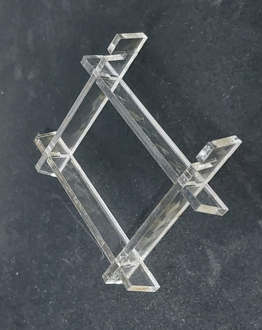
Making a Stand
In addition to the board I wanted to make a small and simple stand to hold the boards upright for people. I wanted to make it small so I could send it easier, while also being easy to manufacture and later assemble. I decided on laser cutting some parts from 1/8" (3.1 mm) thick plastic, since I have a few friends that can arrange this for me.
My final design was a set of four interlocking pieces that the board simply slides into. Two parts hold up the board, and the other two are used to hold them 50 mm apart. This was my first time using FreeCAD so it took me a bit longer than I would have if I was using SolidWorks or Inventor, but I think the results are nice anyways. Might need to brush up on how to make nice drawings though.
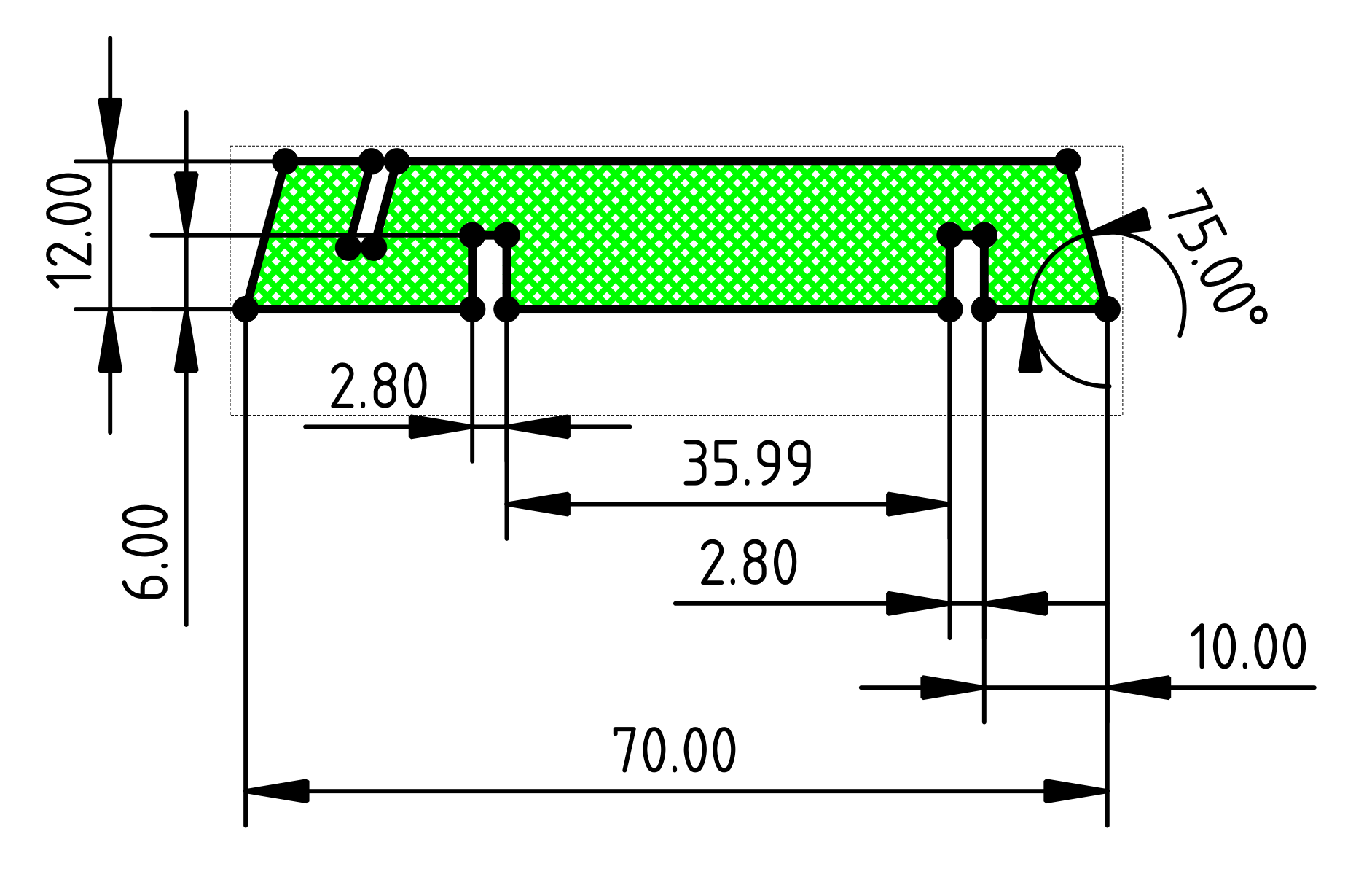
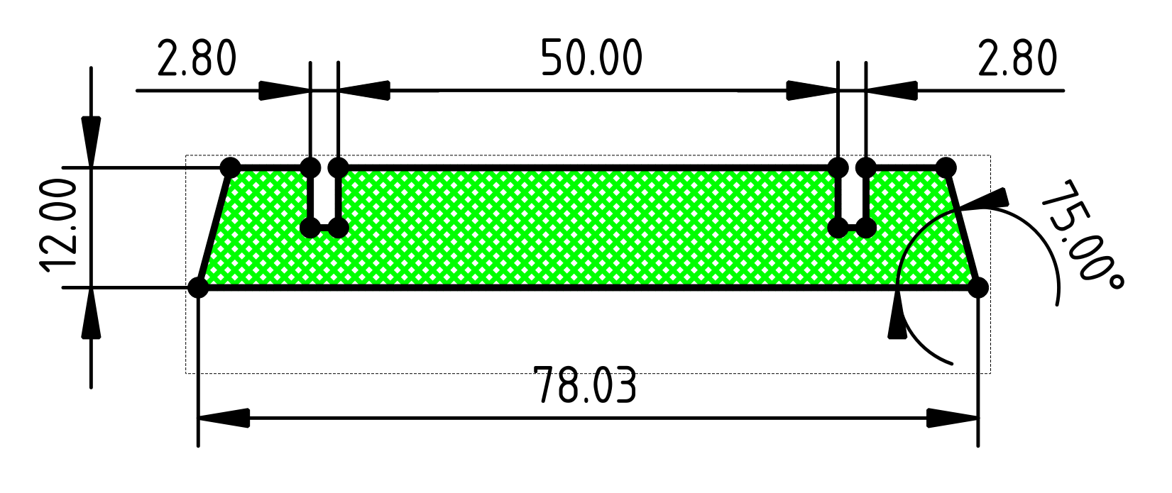
I made one round of prototype parts to see if the width of the slots was just right. They were a bit loose so I narrowed them and the results were just right as shown below. (These final dimensions are reflected in the drawings above.)
Conclusion
With the stands designed, I had my friends cut the remaining pieces for me and I started handing them out! Everyone loved them, and as I mentioned I even had an actual c u s t o m e r!
Reflections
As I write this, it has been almost a full year since I made the first boards in March of 2022. As far as I am aware, none have required a battery replacement yet! So I think my estimates were pretty good. Here’s to hoping these raccoons don’t need a change anytime soon. I’m updating this article largely due to my submission to Hackaday’s 2023 Low Power Challenge where I noticed some mistakes and updates needed addressing in this article.
Look Ma, I’m on the Newsletter!
After my submission to the challenge my project was featured in the Hackaday newsletter for February 15th (2023)! This felt amazing, and I hope to make it back on it again in the future!

My sister was a bit miffed that all credit seems to go to me.