Remotely Operated Amphibious Electric Vehicle
Table of Contents
Overview
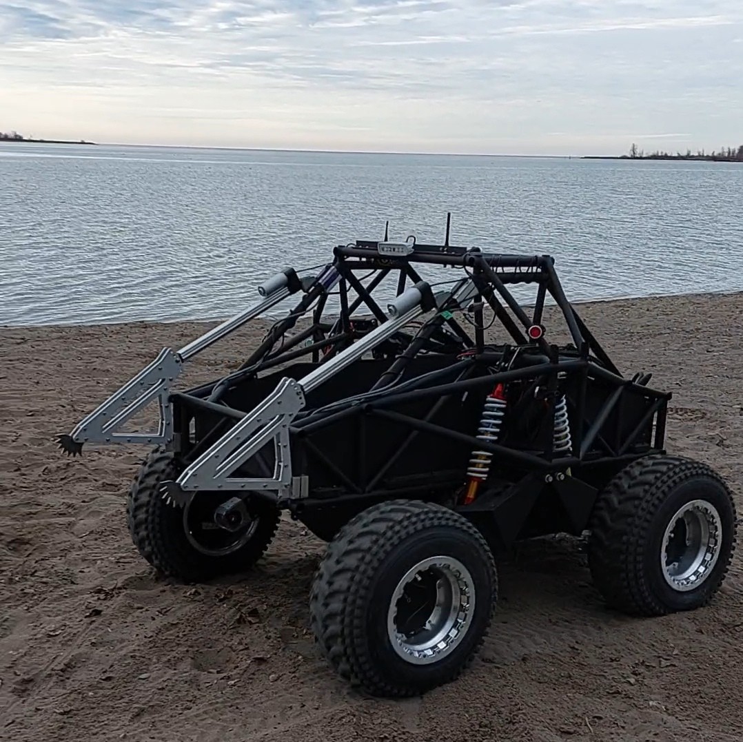
Whelled Arctic Lander - Low Emissions, abbreviated to WAL-LE, was a proposal Engineering Design Lab did for the Canadian Department of National Defense. The request for proposals was looking for a new vehicle to support Canadian operations in the arctic where bringing materiel inland from ships is difficult due to the absence of ports and the rough coastline.
EDL’s proposal was an amphibious electric vehicle that would be hoisted on and off ships with their cranes. EDL emphasized the simplicity of the EV design bringing many benefits to reliability, some of the benefits of the design that were presented to reviewers were:
- Simpler design reducing complexity of maintenance
- Highly symmetric design reducing the amount of parts needed to keep on hand for repairs
- No hydraulics or liquid fuels required further simplifying upkeep
- Range of the purely electric vehicle could be extended with fuel cells or generators if needed
- Use of differential thrust steering (like a tank) instead of mechanical steering (like a car) would reduce the number of mechanical parts needed to operate
This contract was to be performed in phases beginning with a proposal stage, for which as part of EDL’s submission it was decided to build an approximately 30% scale model which would be operated remotely. Thus I was brought in to aid in the electronics of the prototype system. I ultimately was responsible for the entirety of the code that operated the vehicle and its base station, as well as the majority of electrical system integration and troubleshooting both on the bench and in the field.
Design
I was brought in at the start of November when the project was already underway. EDL tasked another designer with the electrical system and a majority of the electrical hardware architecture and selection was decided by him, and the central board designed by him, all largely independently of me. My design contributions was the code for the system the other engineer outlined, where I had complete creative control.
Vehicle Code
This commenced by preparing code template for the vehicle to operate with on the microcomputer and test out key features incrementally. In approximate order of implementation:
- Networking for receiving commands and responding with vehicle status information
- Operating the hardware interfaces on the computer: CAN, I2C, GPIO
- Logging vehicle data
- Developing the driver for the main board in the system
- Developing the land motor drivers
- Outlining the the vehicle behaviour model
- Writing drivers for the aquatic motors
I started this project remotely, which is why I began with “higher level” functions and then developed hardware specific portions when I returned to Toronto and had access to EDL’s facilities and WAL-LE materials. Much of the coding for the vehicle was pretty hassle free, other than dealing with some oddities regarding the operation of the aquatic motors, nothing really surprized me.
Although I ran bench top tests of my drivers with key equipment (motors, main board) to success in December, we had yet to actually test this on the vehicle so it was mostly an academic exercise until it was unleashed on the complete system with everything installed at once.
Base Station Code
In lockstep with code being developed for the vehicle I also had to prepare a base station to enable remote control of the vehicle and ideally relay key information to the operator.
To keep my work on WAL-LE simple I intended to load most of the computation regarding control onto the vehicle itself, the remote station would be little more than a terminal for information to enter of exit the system. In the end all it did was send the vehicle the state of the operator’s remote (buttons pressed, etc.) at regular intervals and then display and log any status information it received from the vehicle.
I considered developing some nice graphic user interface for us to use, however I decided to simply use a terminal based interface augmented with escape characters to allow me to make it nicer than just a stream of text. I could colour text, and erase certain regions to update the interface for the user, among a few other nice things I didn’t know about but now notice in terminal based programs.
Unfortunately I didn’t take a photos of the terminal in action :(.
Integration
Where things really start to test you as much as you test them. Honestly the integration largely progressed smoothly especially with the help I got from the other electrical designer. This began in the first week of January when the chassis arrived.
Electronics Bay
It first began with building the electronics bay into the centre of the vehicle’s hull. Here there were different physical levels for the different voltage levels that were isolated from one another to prevent shorting during assembly and operation. At the bottom was ground (0 V), then 48 V, with control electronics (largely 3.3 V and 5 V, some 12 V) on top for ease of access.
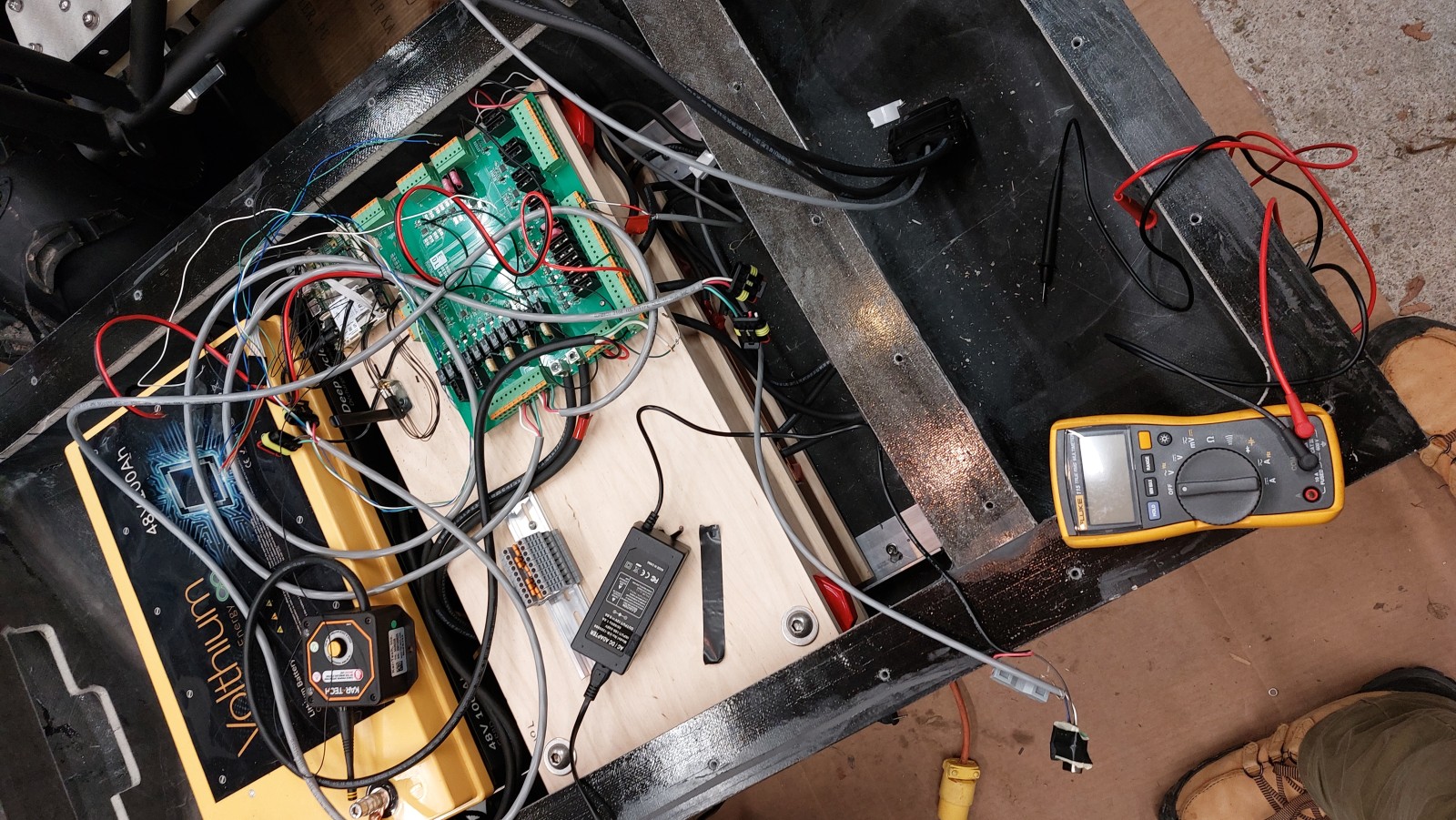
Routing Cables
Following that we ran and routed cables to all the components: motors, lights, actuators. This part was a lot of grunt work, stripping and crimping wires, during which I made an effort to mark different wires and crimp in patterns that would minimize the likelihood of damage in the event things were plugged in incorrectly.
Once we had everything wired up we started running some systems tests to ensure things were working the way we expected. We observed some minor issues in the system here, the biggest being the emergency stop system not operating correctly which required a bodge wire to properly cut power when commanded to.
With the wires in place I progressed to configuring the system in greater detail and calibrating my code to make sure that it would work as expected, for example adjusting flipping the settings for linear actuators so they wouldn’t have their extensions be reversed.
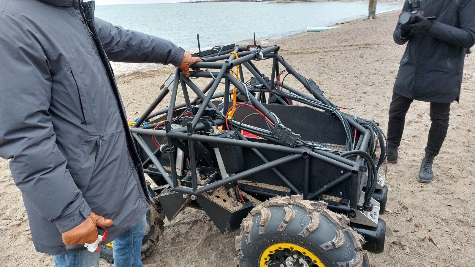
As part of the overall strategy of a gradual bring up of WAL-LE (as well as some logistical hassles), the aquatic motors and their controllers were not installed until after the initial rounds of beach testing.
Aquatic Motors
After the first two rounds of beach testing we added the aquatic motors to WAL-LE. They were omitted in earlier testing to allow us to focus on the validating the core system and improve the land manoeuvrability of the vehicle since that was expected to be both more difficult to tune and also critical to getting right. Little did we expect of the troubles that they would cause us.
EDL had ordered two identical aquatic motors, so that a left/right differential thrust system could be used to steer WAL-LE in the water. When I tested my driver code with it in December I unpacked one of the motor/controller pairs for my test, and it worked flawlessly spinning up both ways on demand as I commended after executing the startup sequence. When it came to installing the second motor and controller pair, we encountered several odd problems that had to be overcome in the space of about a week. In order:
- The second aquatic motor was not physically identical to the first. It even had additional cables.
- The manufacturer assured us that it was a different revision (older) and would operate identically to the first
- Given our tight timeline we gritted our teeth and didn’t allow ourselves the time to debate this with them
- The second motor controller was improperly configured from the factory and would not operate either motor we had
- This was no way for the user to correct this in their documentation
- The manufacturer acknowledged this and express shipped us a replacement controller while we sent our defective one back
- The second motor often failed to start spinning and stall if running at low speeds
- Manufacturer insisted it was because we were running them in air instead of water but the issues persisted
- They suggested we perform a “burn in” procedure to shake off any oxides that may have built up on the older motor as it sat in storage. We did this for several hours
- The procedure allowed it to start and spin reliably but only in one direction, it would fail to start in the other 50% of the time
- Motor only spun in one direction
- We reached out to the manufacturer but they said it made no sense, which to be fair, I agreed with
- Ended up installing the motor so the reliable start direction would propel WAL-LE forwards
- Disabled aquatic motor reversing in software, so WAL-LE could only go forwards in water
Testing
During the integration process there was constant testing of each subsystem integrated. Once enough of the system was brought online, we began small scale motion tests in the lane way adjacent to our assembly site. These eventually led to our three main test days at the very end of January and start of February on a beach in Toronto to approximate some of the expected operating conditions. The first two were purely land tests, the third and final day was our aquatic test.
The constant testing during integration meant that technical issues were all detected and solved very early on before the system got too complicated and would make root cause analysis difficult to conduct. So all the systems came online pretty swiftly, with minimal hassle other than some tuning.
As a result our larger test days were able to focus on the holistic system behaviour rather than individual system issues. This was important since we found it took some time to tune the piloting experience into something that was simple and intuitive.
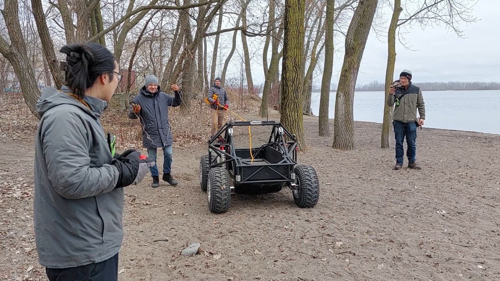
Land Tests
During these initial tests when we were more unsure of how WAL-LE was going to be piloted we had it tethered so it could be pulled back after an emergency stop.
Some of driving feedback from our initial tests led me to change the way our land wheels were controlled. The land wheels could accept either a power level as a percentage or a wheel speed in RPM to set their rotation, and initially I selected to use the RPM option since I thought it would make the differential steering easier to do. However it was found to be slow to respond and a bit sloppy so we experimented with the power option which was found to be way more direct and just as intuitive for the operator.
To control WAL-LE the operator used a standard gaming controller, which had different actions mapped to it. One of the thumb sticks was used, to both steer and control the throttle of WAL-LE. This meant that it was difficult to have it “crawl” at a slow speed and the operators would often over throttle because of how small that range of motion was. This resulted in WAL-LE often digging its wheels into sand instead of moving along.
My remedy was to partially decouple the throttle from the thumb stick. The thumb stick still handled both steering and throttle - but limited to about 20% maximum throttle. A trigger was then used to further scale this to the full range based on how far it was pressed. This made crawling much easier and the system very easy to pick up, at the end of the day we had some team members start piloting WAL-LE reasonably well within minutes.
Most of the fixes and tweaks I’ve described as a result of the testing were deployed on the fly, using over the air updates from my laptop which did double duty as the WAL-LE base station so I could monitor the system for any issues that got flagged. It worked pretty well, although typing with bare hands resting on my metal laptop case meant they got cold fast in the freezing temperatures.
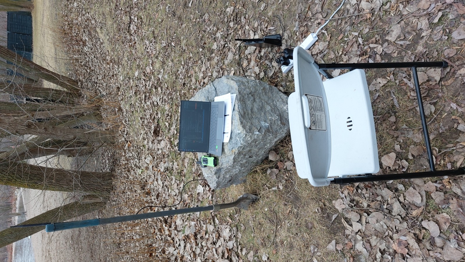
When we got to aquatic testing, I relocated and upgraded my ground station slightly to use a toolbox as a table since I needed to be closer to the shore to ensure a steady control connection.
Aquatic Testing
This one was honestly pretty nerve wracking for us since if anything went wrong there was a possibility that WAL-LE would sink into Lake Ontario. So we made sure that everything could be as tested as possible before it entered the water, especially in light of my issues with the aquatic motors. I still remember the collective breath we all took as it drove in the first time.
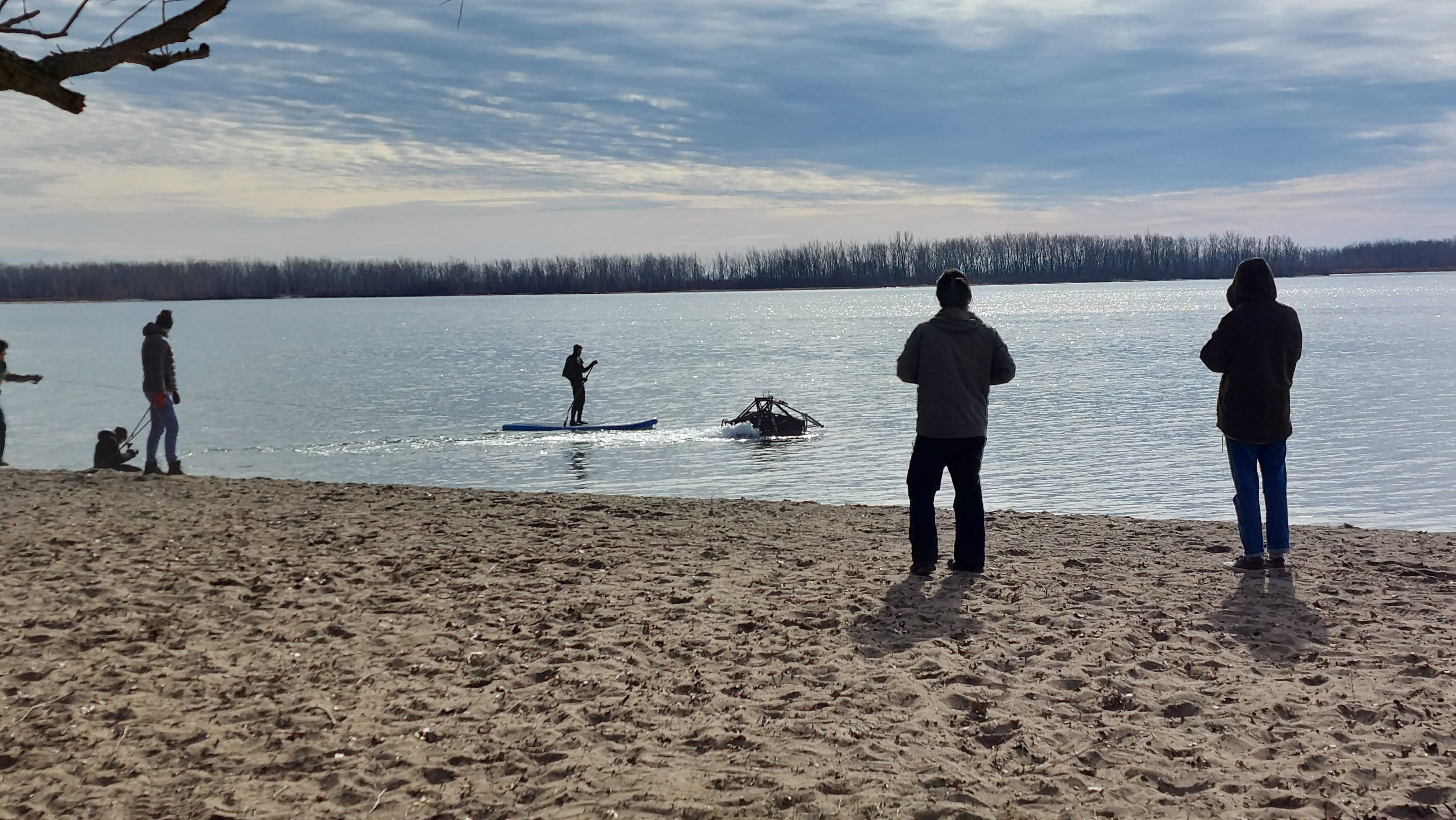
Thanks to all our preparation, the tests went fine and we ended up doing a few passes of WAL-LE entering and exiting the water with a bit of manoeuvring in the water! Aquatic motor funkiness be damned!
With the aquatic functionality of WAL-LE verified we progressed to the rather boring aspect of compiling our report for submission.
Documentary
As part of the submission as well as some PR for the company, EDL had a documentary on WAL-LE commissioned. I feature in it a bit and it shows some of how the project went down and some footage from our tests!
Outcome
In the end the project was a success! Our report was reviewed and we were selected to proceed to the next stage where we are required to build a full scale version of our design, so about three times larger in each dimension and capable of carrying a proper payload the Armed Forces would expect.
This work commenced around April 2025, at which point I was already departing EDL so my involvement was limited to reviewing some design choices and offering advice to the team as they recommenced work on WAL-LE. I wish them the best and you can probably find updates from EDL directly on their website or social media posts.