Overview
This is by far my most complicated project I have undertaken and led for the University of Toronto (UofT) Human Powered Vehicle Design Team (HPVDT), a human powered aircraft. Granted it wasn’t going to be powered by electric motors but there was a lot of data that needed to be collected and processed in a reasonable amount of time, as well as implementing a digital control system for the aircraft!
Overall there were three main systems operating aboard the aircraft:
- Sensor system - To gather data regarding the state of the aircraft in flight, e.g. altitude
- Control system - Gather pilot inputs and actuate the control surfaces accordingly
- Vision system - Provide the pilot’s with an uninterrupted view of the aircraft’s exterior using video cameras and augmented reality (AR) goggles
Each of these further broken down into individual submodules. The sensor and control system are heavily interlinked, both out of simplicity and necessity. So we’ve generally called the two of them combined the “embedded” system since these will be embedded at key points in the aircraft and involved us designing custom hardware for them. This division between the embedded and vision system is also helpful since this allows for the either of the two systems to be changed significantly without impacting the other so long as they continue to respect the communication protocol bridging them.
This project coincided with an influx of members interested in electronics for the team so I have largely delegated most of the design work and have mostly spent my time mentoring people through these tasks and jumping in to help when needed rather than delivering projects start to finish as I had for most of my other work for HPVDT.
Embedded System
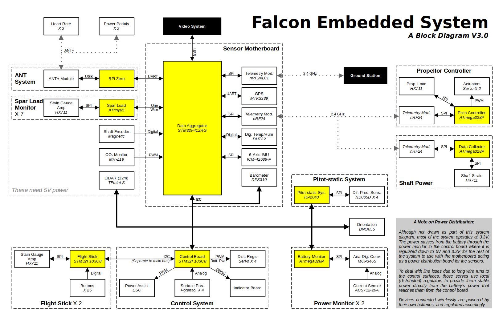
The embedded system is the combination of the control and sensor system. It’s composed of several circuit boards designed for specific purposes placed around the aircraft to collect data or actuate our control surfaces. Below is a block diagram of the entire embedded system, in it the white blocks are modules used to acquire or relay data, yellow is for microcontrollers that we will program with our own firmware, and black for other systems outside the scope of the embedded system.
Control System
The control system is critical to the operation of the aircraft - without it the pilots will have no way to steer the aircraft (unlike larger aircraft with cable/hydraulic backups if the electronics fail). For this reason the system was designed to be as simple as possible and to be able to continue operation in the event any other systems fail. It is composed of three main board designs:
- Flight stick - Reads the state of a flight stick and forwards that to the control board for interpretation
- Control board - Converts the pilot’s flight stick inputs into commands for the control surfaces
- Servo regulators - These are distributed near the servos at actuation points to locally regulate power to safe levels to reduce wire losses and counter the associated voltage drops
To communicate among themselves these boards use a separate I2C bus and point to point PWM so that only a failure in the control system itself can impeded its operation. The main control board does have a connection to the main I2C bus so that it may forward the flight stick inputs on request to the video system via the motherboard. The control system even has a small simple display of LEDs used to continue informing the pilots of critical control states in the event the main video system fails.
The main control board has a couple other minor tasks it fulfills. Firstly, it serves as the main power regulator for the embedded system, providing up to 2 A on 3.3 V and 5 V rails. This way if the connection between it and the sensor system is severed, it will be able to continue operation without them.
By having access to the main communication bus, the control board can also potentially tap into these sensors directly to allow us to develop self-levelling or heading holding control algorithms to simplify things for our pilots down the line. This is not considered for any of our initial flights though! Those will just have direct flight stick to control surface relations.
Sensor System
The sensor system is in charge of gathering information about the aircraft’s state. This covers a whole mess of data, but some of the most important is the aircraft’s orientation in space and airspeed. To wrangle all this data there are a number of co-processors on boards separate of the motherboard which is chiefly responsible for collecting all this data and forwarding it to the video system to be used in the video system.
At the present the following data is collected by this system:
- Orientation (roll, pitch, yaw)
- Two sensors for this
- Altitude
- Pressure based
- LIDAR based
- GPS based
- Structural strain in main structural elements
- Pilot biometrics (cadence, heart rate, foot power)
- CO2 levels in the cabin
- Pilot inputs on their flight sticks
- Electrical power draw of the embedded and video systems
- Ambient humidity and temperature
- Wind speed vector relative to aircraft (pitot-static system)
- Land speed (via GPS)
- Location (via GPS)
- Shaft power to propeller
- Propeller blade pitch
- Control surface angles
Video System
This is something I’ve not been too heavily involved in yet to be frank.
Since this aircraft is based off the design for TITAN the pilot configuration does not offer a convenient view port for them. There are no ruled surfaces that would make a physical window easy to manufacture, and even if there was, their heads are not located somewhere that would suit them surveying their surroundings. So as a result of this, and the possibility of pursuing remote controlled test flights a digital vision system is necessary.
The basis of the system’s function would be akin to TITAN: show the outside and overlay it with data. The major departure though is that TITAN, and all of HPVDT’s previous vehicles for that matter, have only offered a fixed camera perspective on a fixed screen inside. For the aircraft it was made immediately clear that the video system would need to be 360 degree and head tracking to maximize situational awareness and to minimize the potential motion sickness induced by a video system. This was needed as a minimum for the main pilot, but ideally both pilots would have access to this system.
To achieve this the team is currently employing 360 degree cameras and a set of augmented reality googles with a powerful microcomputer to perform the head tracking.