TITAN 2022
Table of Contents
Overview
For TITAN, our return entry to the World Human Powered Speed Competition (WHPSC) from 2019 our team needed a video system for the vehicle. This system is vital because it is the only way our riders can know what is outside and steer because we do not have windows - primarily to improve our aerodynamic performance. Not only was the system meant to provide a live video feed of the surroundings, but also overlay the video feed with data about the bike’s state, namely speed and rider power output.
I had already attempted a system previously, but I greatly revised it based on feedback from our riders and my improved understanding of embedded systems.
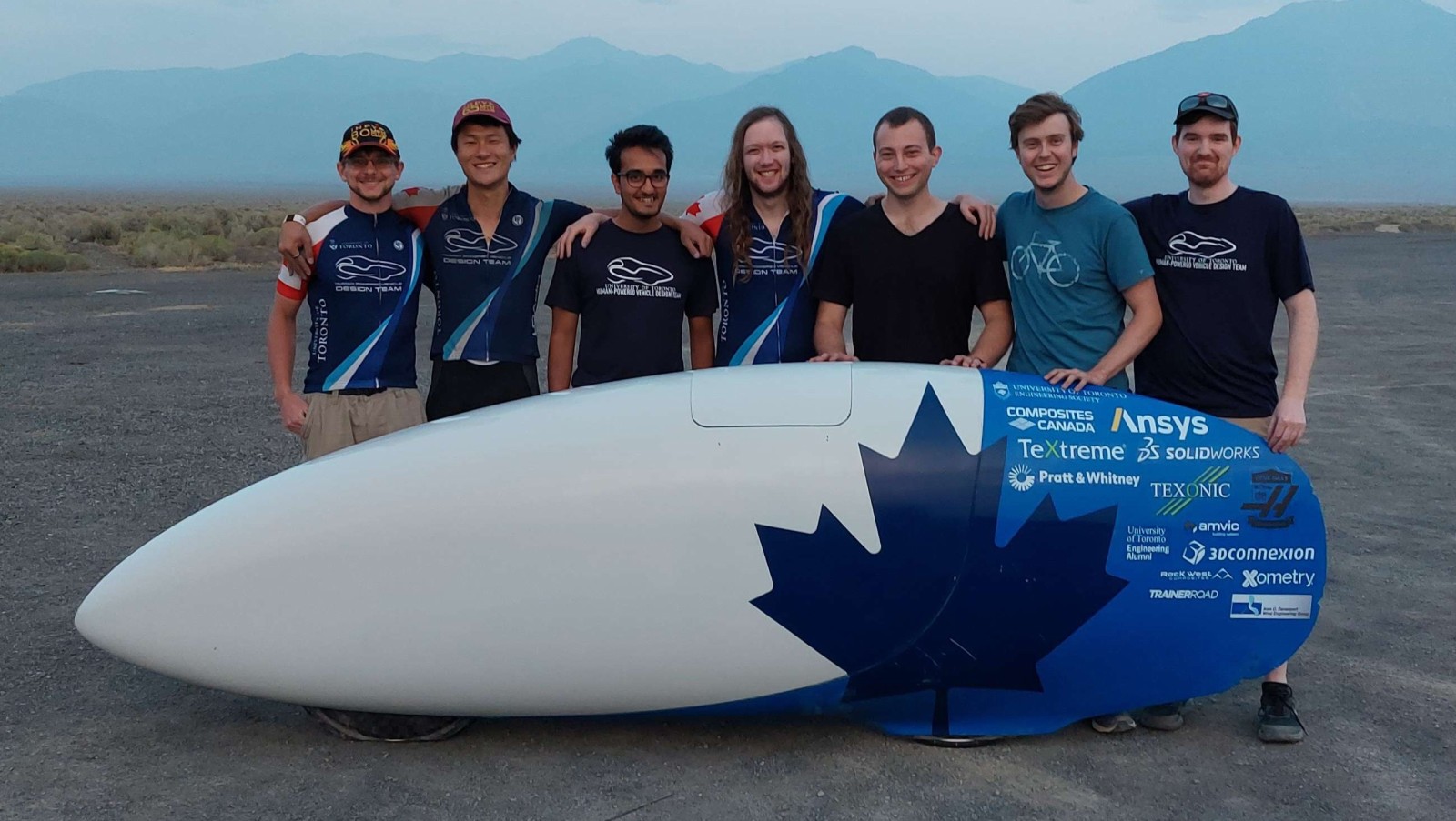
Unlike 2019, I went with the team to help compete at the competition! Although the system had some minor issues in our first few runs which I hadn’t experienced in development, I was able to iron out most issues between each set of runs. Unfortunately we suffered a crash on our third run which ended our participation for the remainder of the competition.
So although we didn’t get to run it much yet, I feel the system was successful!
Reviewing TITAN 2019 Feedback
The first step for this revision was to review the feedback for the 2019 version, main points of which are summarized below:
- One RPi/board pair resulted in a boot loop, likely caused by a poor voltage regulator
- The camera feed would flash black periodically, caused by the overlay updating process.
- The rear facing camera was useless
- Use a direct camera-screen setup for the back-up video feed
Requirements
The requirements for this system are essentially the same as they were for TITAN previously.
- Have three displays, each running a separate video feed running off seperate power sources.
- One front facing “main” display for front rider
- One front facing “spare” display as a redundant video feed for the front rider (does not display bike data)
- One “secondary” display for rear rider (can be either front- or rear-facing)
- Gather and relay the following critical data to the riders
- Bike speed
- Distance travelled
- Cadence (rate of pedalling) per rider
- Power output per rider
- Video feed must be stable and run at a minimum of 30 frames per second
Objectives
The objectives did not budge much from the original TITAN objectives either.
- Gather and relay additional non-critical data to riders
- Stream data to chase vehicle
- Record video feed
- Log all collected data
- Inform users on the estimated “performance” of the run relative to expectations
- Reduce system footprint from previous iteration
Takeaways
There are a few takeaways I have from this project.
- Locking connectors are very useful, crimping wires is a quick way to assemble a harness too
- Communications can be greatly improved by using “binary” (non-human readable) data, both for speed and reliability.
Detailed Report
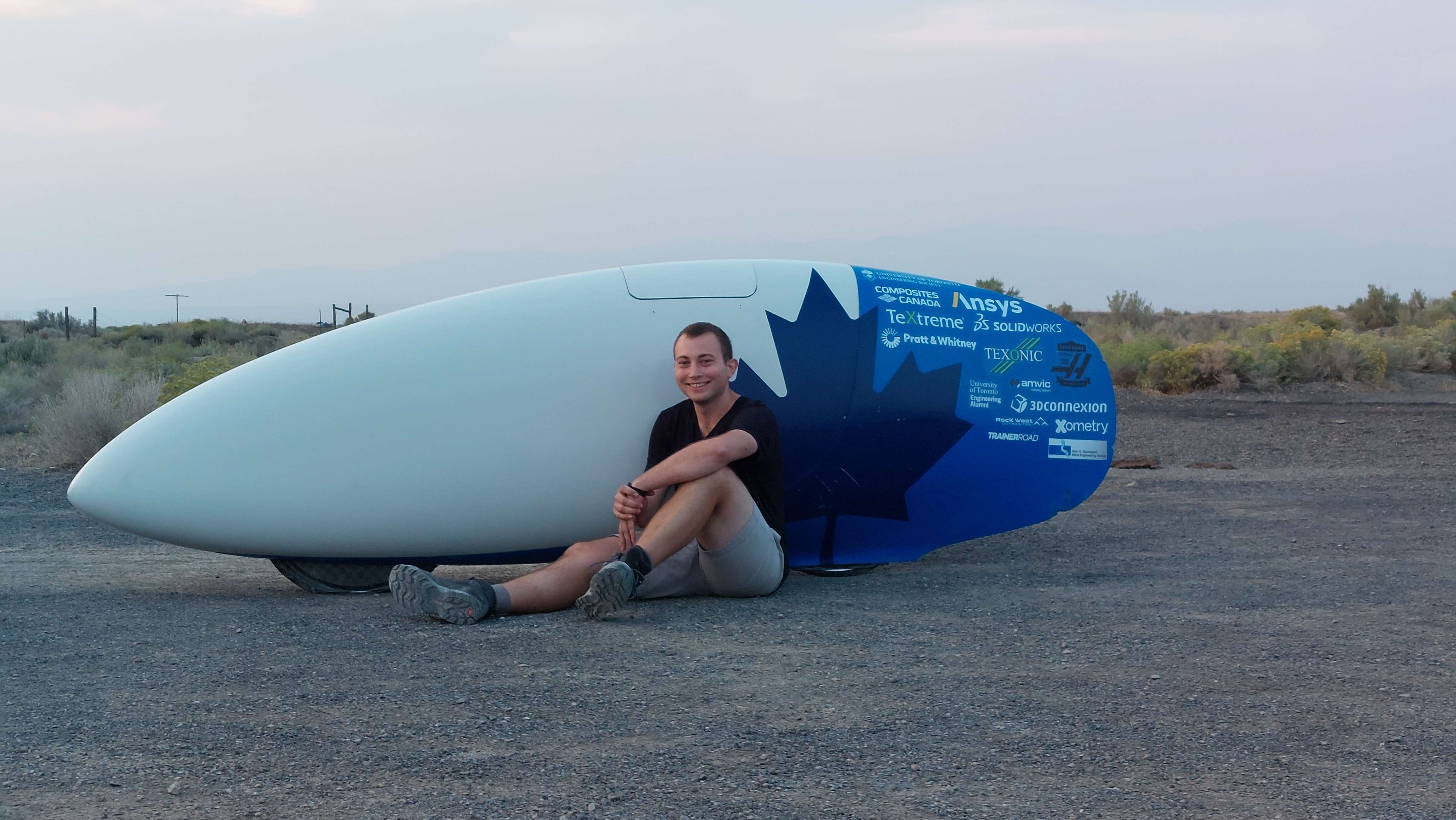
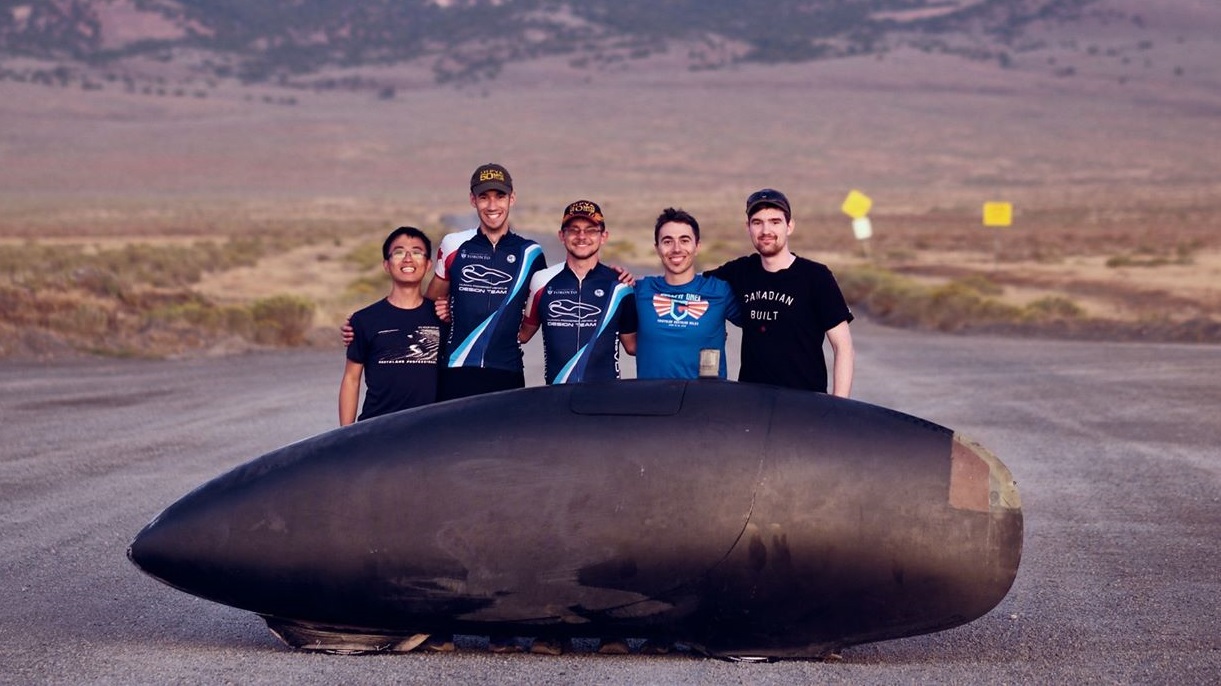
For our high performance speed bikes we pioneered the use of a video feed in place of a conventional window to see out of our vehicles. This approach provides us with a couple of advantages, namely improving our aerodynamics by allowing more recumbent riding positions for our riders (closer to laying down than sitting) which decreases our frontal cross section, and the removal of a window removes numerous seams between the window and fairing that could contribute to disturbing laminar flow over the remainder of the fairing increasing drag.
In the place of a window, a camera (in a mast is placed outside the vehicle) and a display inside the vehicle provide the view of the surroundings for the rider(s). On TITAN the mast is the black protrusion right behind the hatch.
The vision system is also used to relay information about the vehicle to the riders, like speed, using overlays on top of the video feeds. This makes it trivial for the rider(s) to check how the ride is going since they do not have to greatly shift their focus from the screen to do so.
Overall System Design
My system scope design didn’t change massively from my previous design.
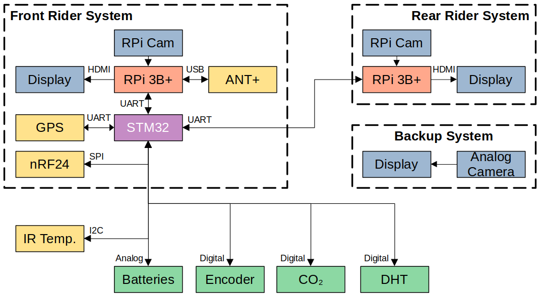
There would be three cameras used in TITAN, two for the front rider, one for the rear. All of these would be front facing; two of them would be digital cameras (one for each rider), and the third an analog camera (spare for front rider). This is slightly different to the previous system where all the cameras were digital and the rear rider had a rear-facing camera. The switch to analog was done to simplify and thus improve the reliability of the redundant screen for the front rider by minimizing possible points of failure. The switch to have the rear rider’s camera face forward was done since our rear rider found a rear facing system useless and found that using a front facing display was more comforting.
For the digital camera systems I reused the Raspberry Pi 3B+’s and Raspberry Pi Camera modules from the previous system. For the analog system I used a commercial analog camera fed directly into a screen. For data collection and communication between the RPis I used an STM32 microcontroller like I had previously.
In the end the basic block diagram was drawn up to be the following. My choices will be explained in greater detail in the sections that follow.
Raspberry Pis and Pi Cams
We used Raspberry Pi 3B+’s and Raspberry Pi camera modules for the digital camera systems. As mentioned before, in addition to outputting high resolution and frame rate video (720p at 60 frames per second) the RPis serve to overlay data on top of the video stream as well as recording the video stream for later review.
I kept using these since they were easy to use, I already had some code prepared for them, and most importantly - between 2020 and 2022 we had them on hand during supply shortages of just about any electronics.
Displays
I reused the displays used previously on TITAN since they all still met the required resolution and frame rate requirements we needed. In addition to them all accepting HDMI, they also accept analog video input so changing the redundant front screen to run off analog video did not require a new hardware (other than the camera).
These displays are some standard 5" (for the backup) and 7" brandless LCD panels with loose driver boards available from vendors on sites like AliExpress (the vendor which we purchased ours from appears to have closed up shop). We use these since they provide us the flexibility to design our own housings for them which is vital in the constrained space of TITAN.
Microcontroller
The microcontroller’s purpose is to collect data (especially real time) and distribute data about TITAN as needed. I elected to continue to use the STM32F103C8B in TITAN from the previous version. My reasons for this are:
- It fulfilled its role perfectly previously in TITAN
- Enough I/O for all the sensors
- Enough communication peripherals for all the RPis and complex sensors/modules
- Enough clock speed to avoid unresponsive behaviour
- Plenty of program space for all the libraries and routines needed for TITAN
- Familiarity of using it
- Plenty of reference projects online
- Has a designated debugging/programming interface
Sensors
There was a lot of types of data collected on TITAN, I’ll be listing the hardware I used and what data it gathered. They all connect to the STM32 with the exception of the ANT+ module which is connected to an RPi since it needs a USB connection.
A review of the sensors reused from the previous system:
- Resistor voltage dividers
- Battery levels - Used to divide the different battery voltages down to safe levels for the STM32 to measure
- DHT22 (Digital Humidity and Temperature)
- Used to monitor ambient air conditions
- Optical Encoder
- Wheel-based speed - The period between pulses provides the rotational rate of the wheel
- Wheel-based distance - The number of rotations is counted and used to estimate the distance travelled
- GPS
- Location - Not super useful during rides but useful in run analysis
- GPS-based speed - A redundant speed value in the event the encoder is not acting correctly
- GPS-based distance - Using the current location an estimate can be found for how far TITAN has gone, and how much remains to go
- ANT+ Dongle (USB connection to rear RPi)
- Power - Both riders have power pedals
- Cadence - Both riders have ANT+ power pedals also broadcast this
- Heart Rates - Both riders wear heart rate monitors
From the previous version of TITAN, these sensors were added:
- IR Contactless Thermometers
- Brake disk temperatures for front and rear
- CO2 Sensor
Telemetry
To broadcast data out of the bike to our chase vehicle, we used nRF24L01 modules. I had intended to use these back in 2019 but never got around to working them into the system before the competition. Since then I had done some work specifically on this so I now was ready to properly incorporate them into TITAN, the difference from before hardware-wise being that the module would be interfaced with the microcontroller instead of an RPi. This was done to simplify coding for the RPis as well as ideally making the system more responsive.
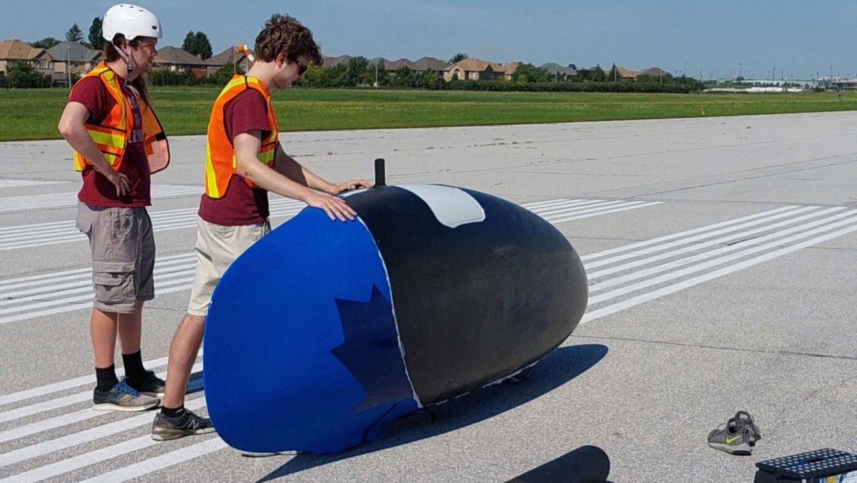
Given that the fairing is largely composed of carbon fibre (which blocks radio waves), telemetry and the GPS both had antennae that were run to the rear of the bike so that the radio waves could escape the fairing through a designated fibreglass portion which permits radio waves. This fibreglass portion is a visually distinct brown next to the black carbon fibre used for the remainder of the fairing.
Circuit Design
Once I settled on the hardware I wanted in the system, or rather what changes I wanted from TITAN, I got going on designing the circuit.
I made two revisions for hardware corresponding with my two main periods of work on this, one in fall 2020 and another in the summer of 2022 leading up to competition to iron out some minor issues with the first. Below is the schematic for the first revision.

The circuit can be broken into a few main sections:
- The 5 V regulator. Includes certain power protections like reverse polarity.
- The microcontroller and communication section (RPis, GPS, telemetry, USB)
- Sensor interfaces
Most of these are based off reference designs for the respective section (e.g. the regulator chip), so there wasn’t too much for me to do other than designating the connections between these. The areas where I did design some circuitry of my own were the power protection stages before the 5 V regulator and the comparator for the analog input.
Revised Circuits
For the second version I changed a few things from the first, major changes listed below. It however largely remains the same.
- Off-boarded the encoder comparator to a separate board
- Added the new IR thermometer and CO2 sensor headers
- Added status LEDs (controlled by microcontroller)
- Added SWD debugging header for STM32
- Changed the 5 V regulator (due to supply issues)

Overall I am satisfied with the final circuit for TITAN in 2022. The only hardware issue encountered was that I failed to add enough capacitance to the analog circuitry for the microcontroller so ADC readings used for battery monitoring were too noisy to be used. This was tolerable though since the batteries were only used for about 20 minutes at a time before recharging but had enough energy when fully charged to run for over 200 minutes.
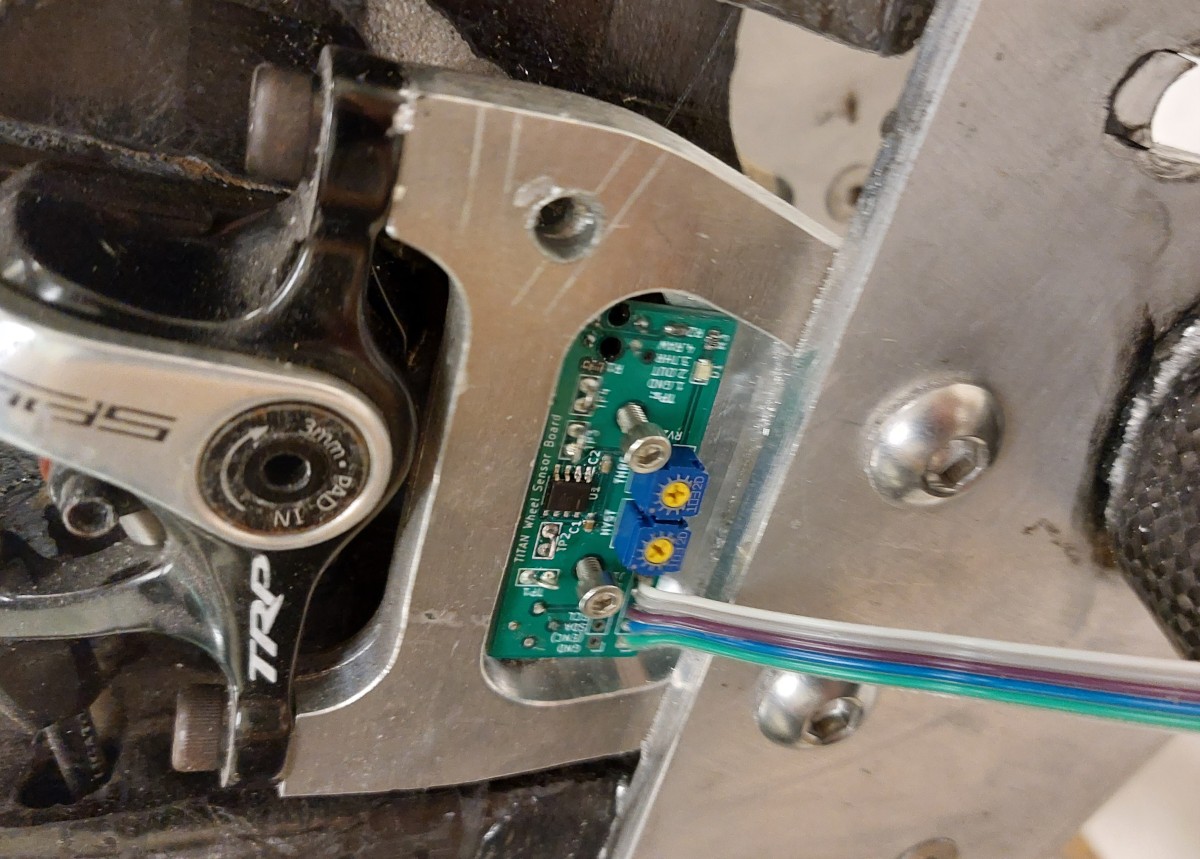
Below is the schematic used for the daughter board used for the rear wheel to house the IR sensor for brake disk temperature and the IR reflectometer used to track brake spokes as an encoder. It has a simple op-amp circuit used to amplify and convert the reflectometer signal into a digital one for the microcontroller, and headers to connect to the rest of the system.

The circuit for the daughter board worked as intended once tuned. The only minor quirk it had was that once the brakes were engaged the IR encoder would fail to accurately monitor rotational speed. This was due to the brake disks heating up enough that the IR emitted by them overwhelmed the sensor. This could be remedied by using a visible light sensor or a different encoder arrangement altogether. However this wasn’t an issue since once the brakes are engaged on TITAN the exact speed is no longer of concern since it has finished its run and the GPS provides a rough speed until the disks cool down.
Board Layout
There were two boards made, the main boards that were put on the RPis as HATs (more on that later) and the daughter boards for the wheel sensors.
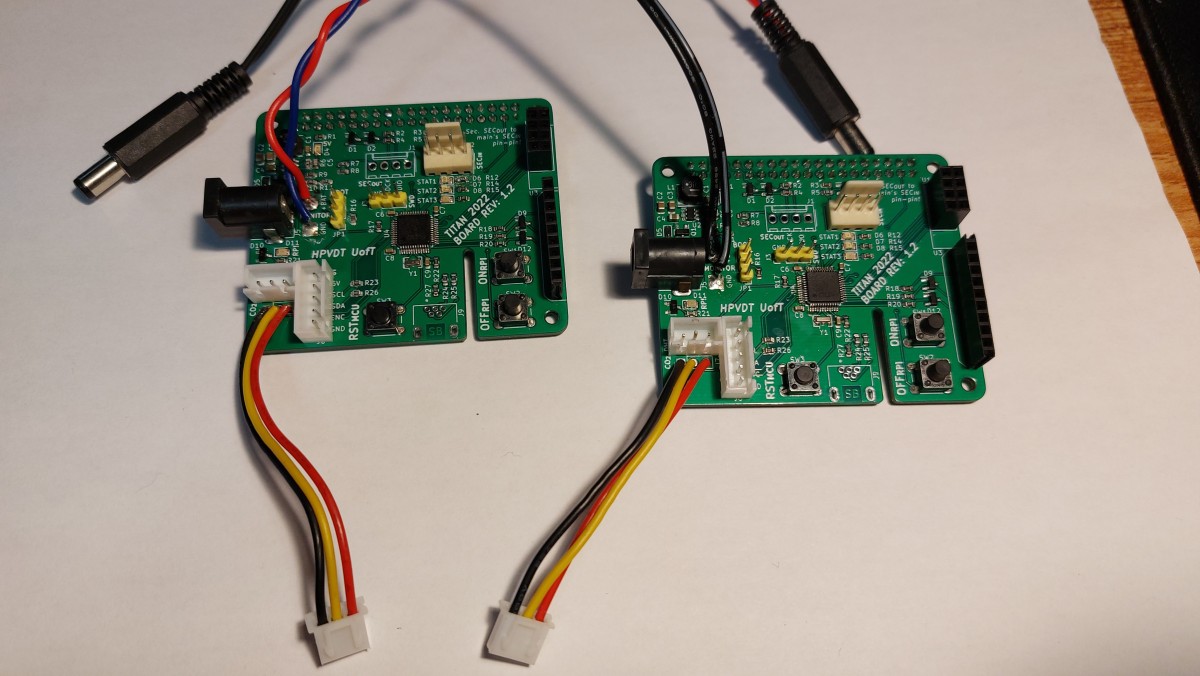
Main Board Layout
The board layout underwent a much more intense change from the previous version than the circuitry. Whereas the previous board was meant to sit completely separate of the RPis connected to them by a 40 wire ribbon cable, the new boards were meant to be mounted using the RPi Hardware on Top (HAT) standard. This eliminated the need for the ribbon cable by putting the TITAN board directly on top of the RPi with a 40-pin header which also reduced the overall footprint of the system by having the board overlap the RPi. This was first attempted with Blueshift to reduce system size as well as reducing the chance of incorrect connection.
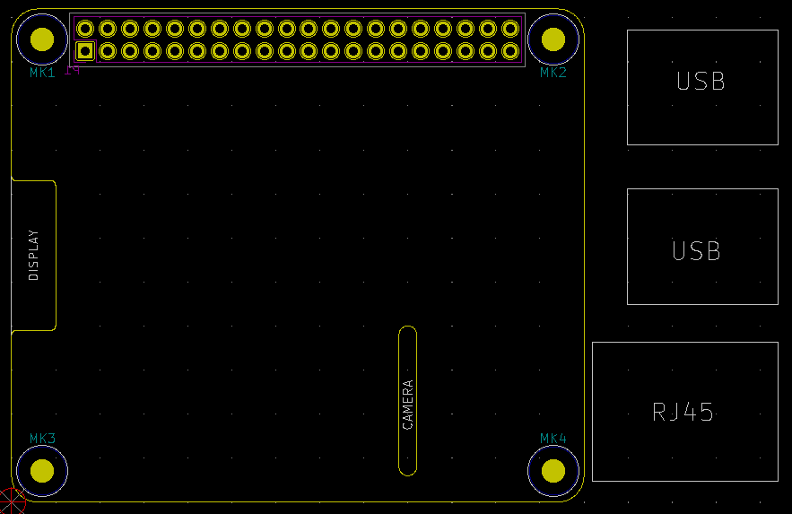
The HAT standard also has a recommended outline to not extend outside the footprint of the RPi (65 by 56 mm), mounting holes to seat nicely on the RPi, and spaces for the different interfaces that might need to pass through; RPi display and RPi camera cables. The default HAT board is shown below, I made two changes to the outline visible when looking at my layouts later:
- I removed the clearance for the display cable on the left edge since we weren’t going to use it. HDMI comes out the side of the RPi.
- I extended the slot for the camera cable to the lower edge. This would allow the HAT to be seated to or removed from the RPi without needing to fiddle with the camera cabling.
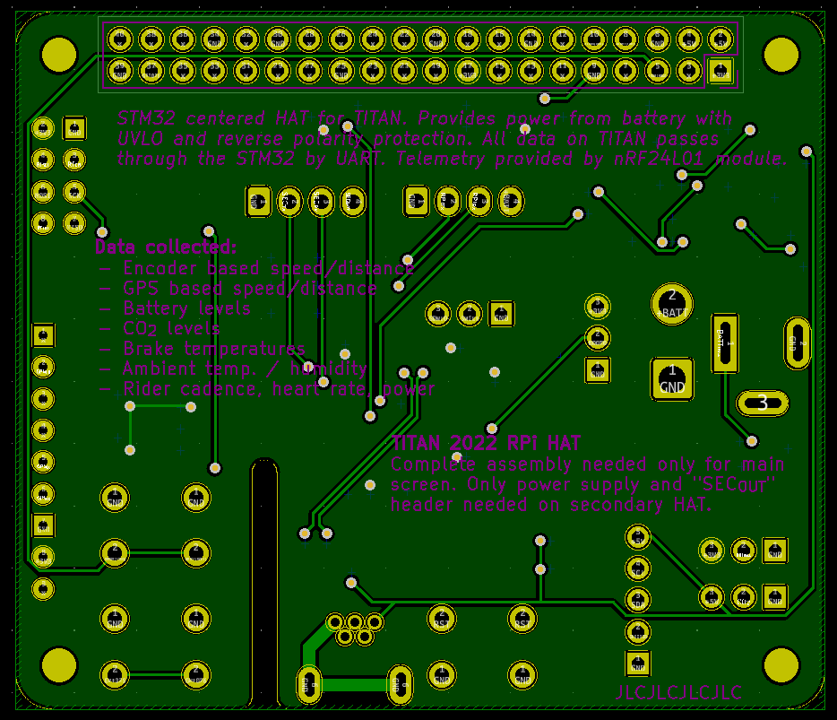
Here is the overall layout of TITAN for 2022. Although all the board itself does not extend outside the boundaries of the HAT standard, there are a few components that protrude beyond the edges. Namely the GPS and nRF24 modules on the right which were placed there intentionally so that they could rest atop the ports there to support their cantilevered boards. They don’t protrude significantly beyond the edges of the RPi itself.
I tried to place the majority of ports around the edges of the boards, and the buttons along the bottom edge to moderate success. There really isn’t an obvious flow to any of their placings though which could possibly be improved on.
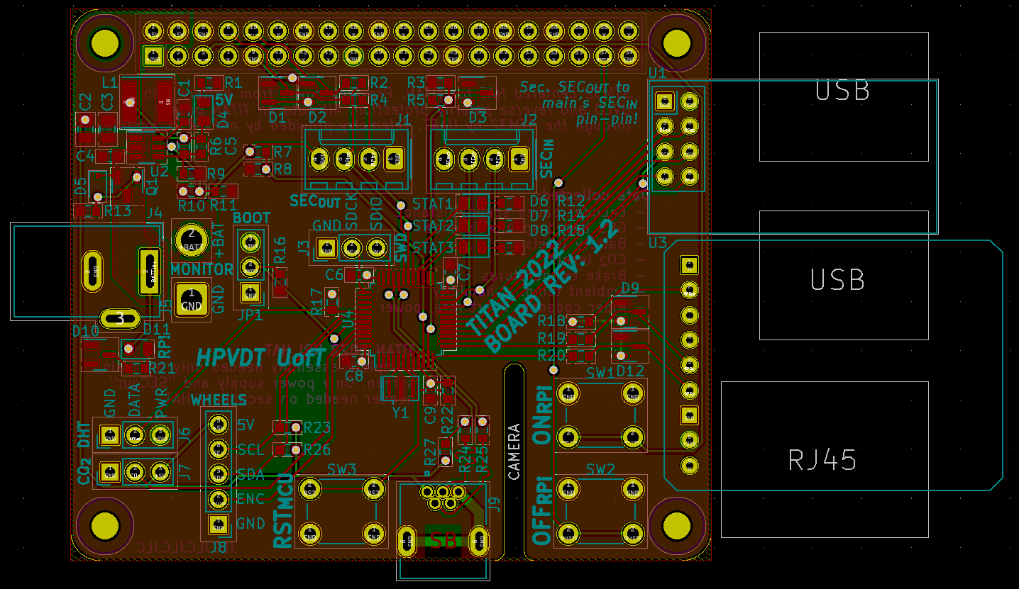
All the hardware other than the header for the RPi resides on the top side of the board. The microcontroller is seated in the middle with the different parts it connects to placed radially around it. The power regulation and protection circuitry is in the top left quadrant since the 5 V pins for the RPi are there so clustering all this there reduces the parasitics present in the power system. Introduced from the previous version, the status LEDs are placed in the centre since I wasn’t too sure which side would be easiest to view when mounted in the bike, so here they would be equally visible regardless of board orientation.
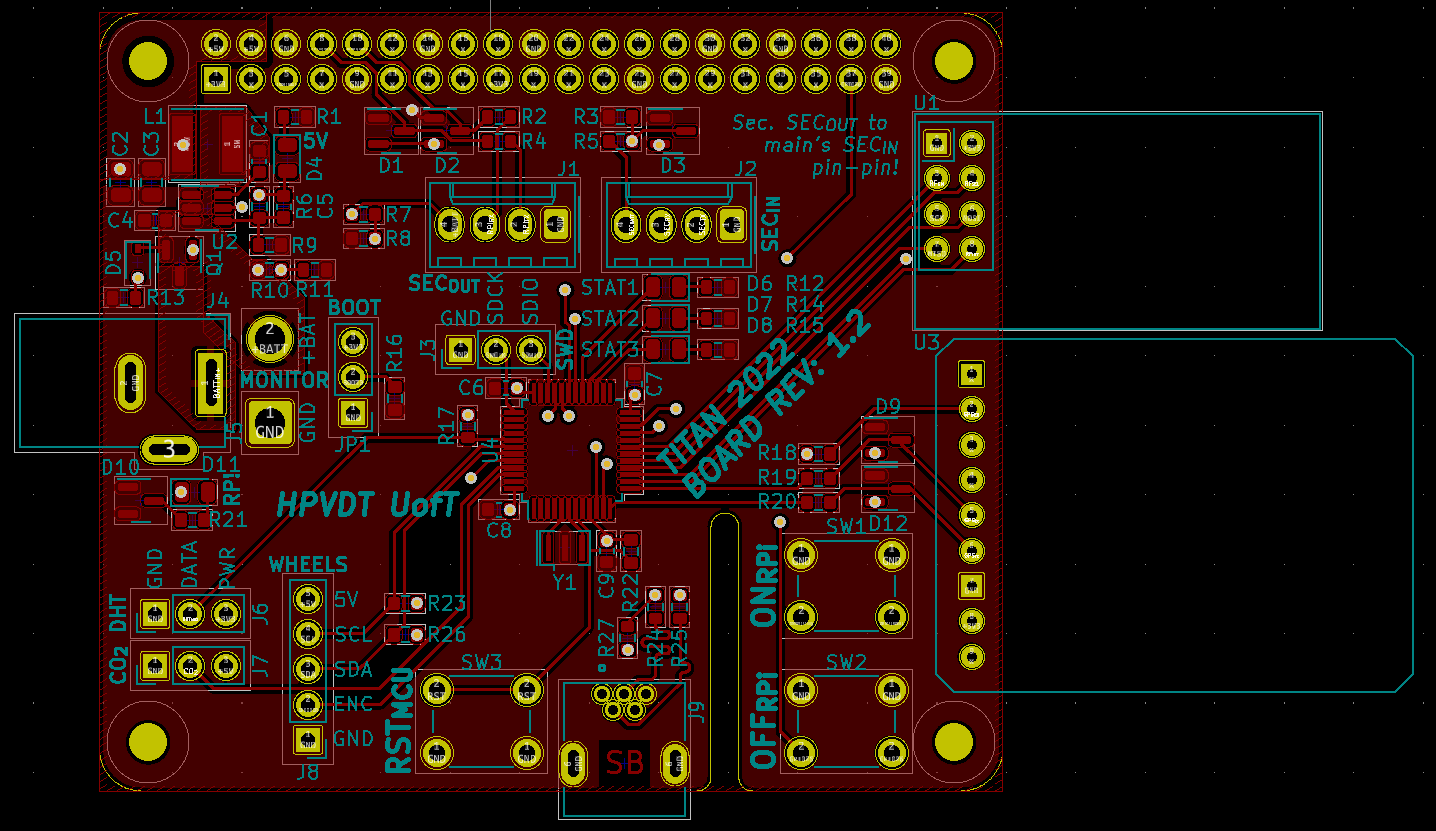
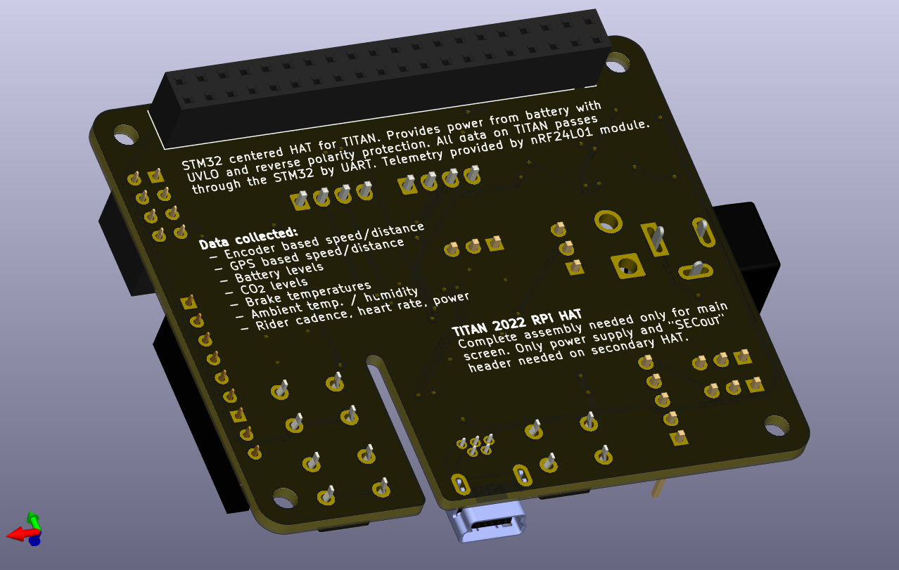
The majority of traces are on the top, the bottom was reserved mostly for a 3.3 V plane and the odd traces that needed to use the bottom. Since it was devoid of parts I used it to record some of the boards features as well as some basic assembly instructions.
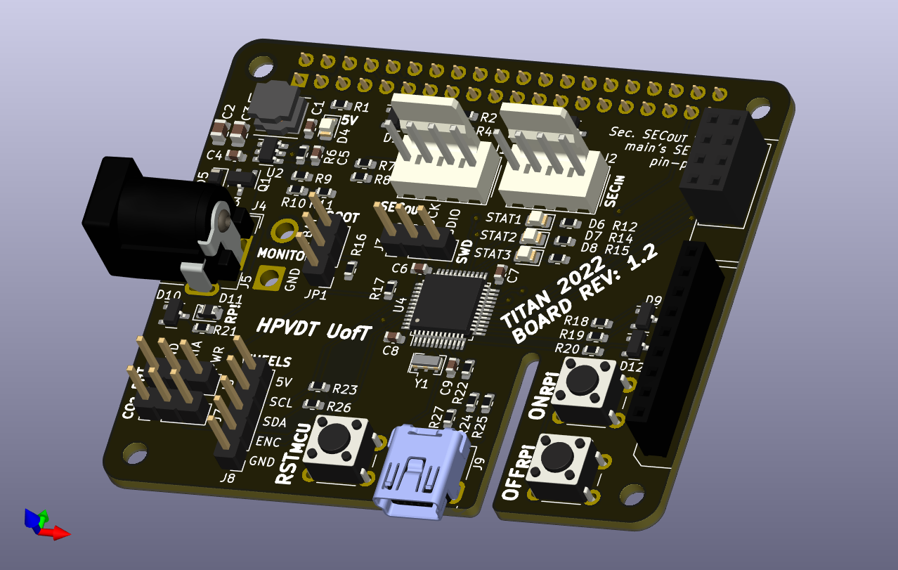
Here are renders of this HAT as it should be assembled. Note: the nRF24 and GPS modules are not modelled in KiCad nor do nice models exist online, so I just have them modelled by the headers they will be seated into.
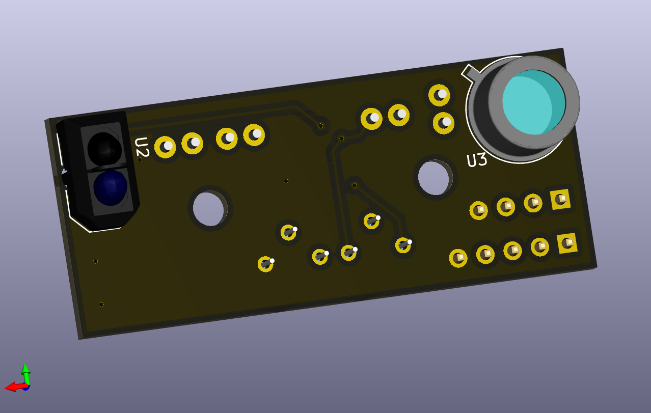
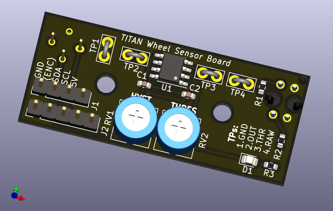
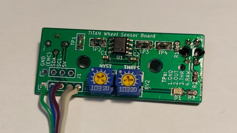
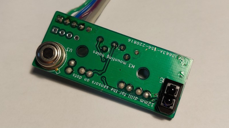
Wheel Board Layout
The layout of the wheel board faced some geometric constraints as it needed to fit inside a pocket in the wheel bracket responsible for holding the rear wheel in place. It needed to be low profile so it would avoid collisions because the rider’s feet would pass right by it as they pedalled, and reasonably hardy should it be struck.
I used some of the commentary layers for annotating the dimensions that the board needed to abide by for the sensor locations. This was needed so we would then know where to drill holes in the wheel brackets to mount these boards properly and have the sensor seat nicely into them.
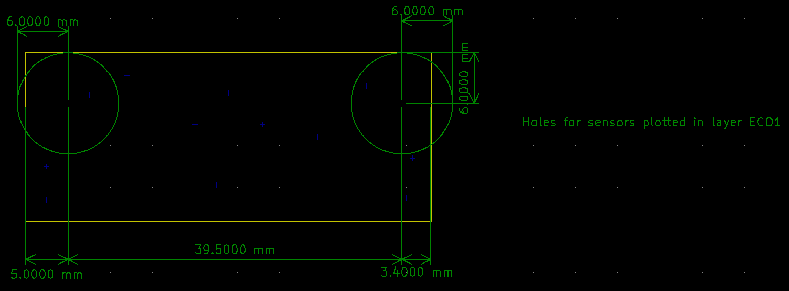
I then built up the circuit around these and the other dimensions I recorded.
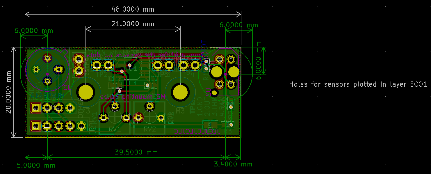
With just the actual manufactured layers (copper, edges, silk screen, etc.) the layout is compact but not complicated.
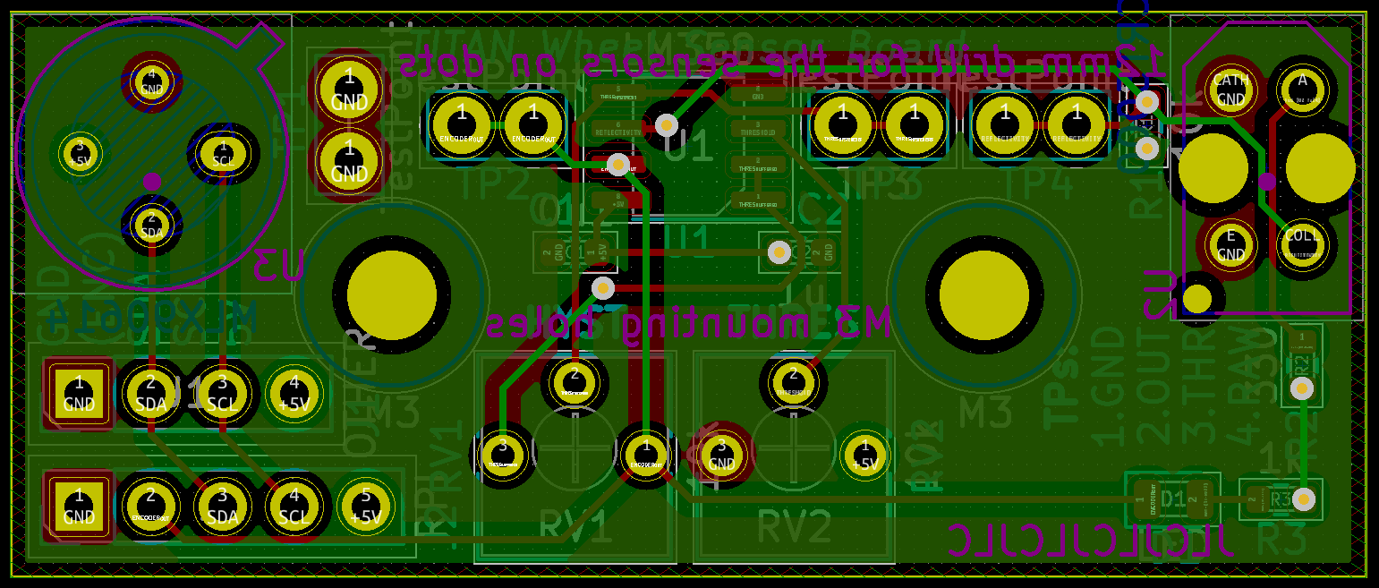
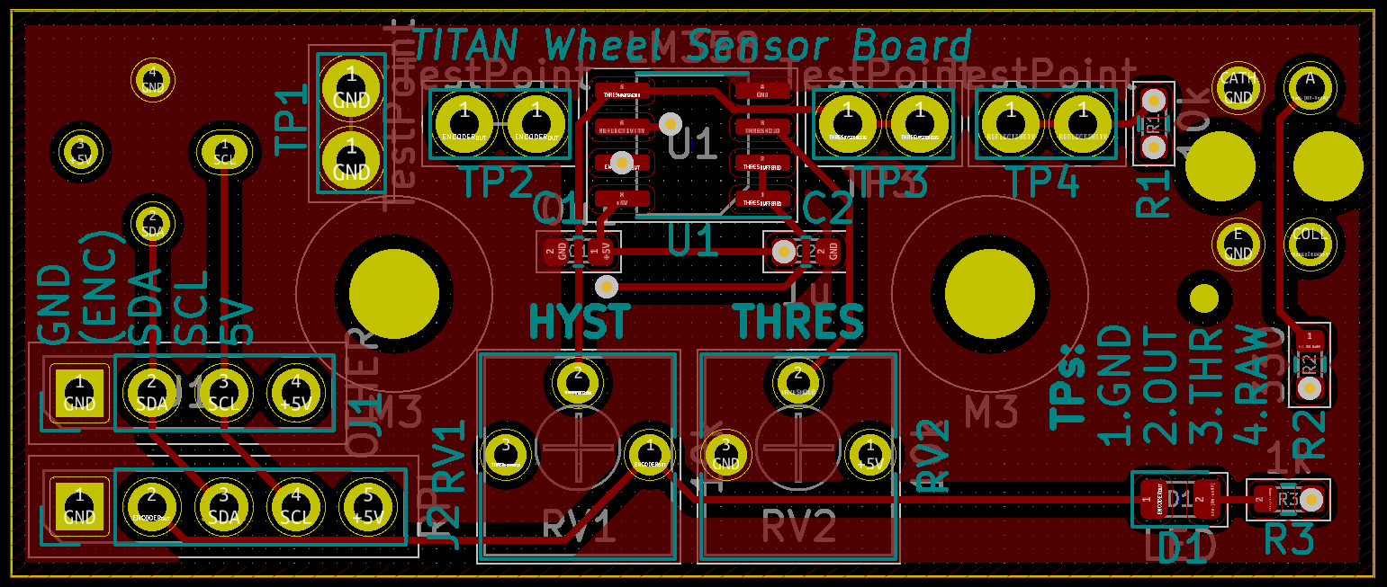
Focusing on the top layers I set the test point for a ground connection to be perpendicular to the other three so it would be easier to identify. I included labelling for their purposes on the board to ease the tuning that would be needed later.
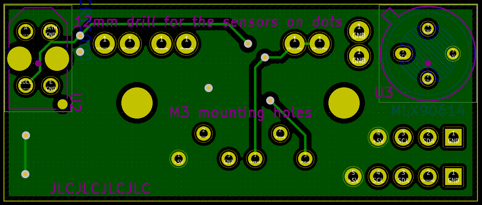
The bottom served as a 5 V plane and had traces for some connections.
Some 3D renders of this board as it should be assembled. Note: I couldn’t find a 3D model for the IR temperature sensor with four leads included in KiCad so I used one with three.
Assembly
Assembly of the boards proceeded without a hitch. Some small changes were made to boards regarding the headers since the team got a 0.100" pitch JST header kit which was used for most interconnects instead of the originally intended 0.100" pitch pin headers since they had builtin locking and orientation ensuring features.
Main Boards
I assembled three of the main boards: two complete boards to have a spare handy, and one without a microcontroller for the rear rider system. I had a stencil for paste that helped with the surface mount portion.
Looking closer at the main board, not all the JST headers could physically fit in the corner for the different sensors because I designed it for pin headers, the CO2 sensor header was mounted offboard on a short cable harness. This had the minor advantage that it allowed me to use the opposite header type to the DHT sensor so that it would be impossible to plug their 3-wire cables into the wrong header, although I did have to pay attention to joint fatigue.
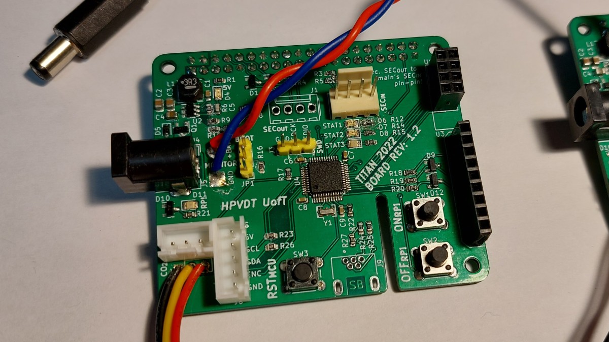
Since USB wasn’t likely going to be used for debugging since I now had the SWD header, I omitted their connectors at initial assembly. (These were never added later.)
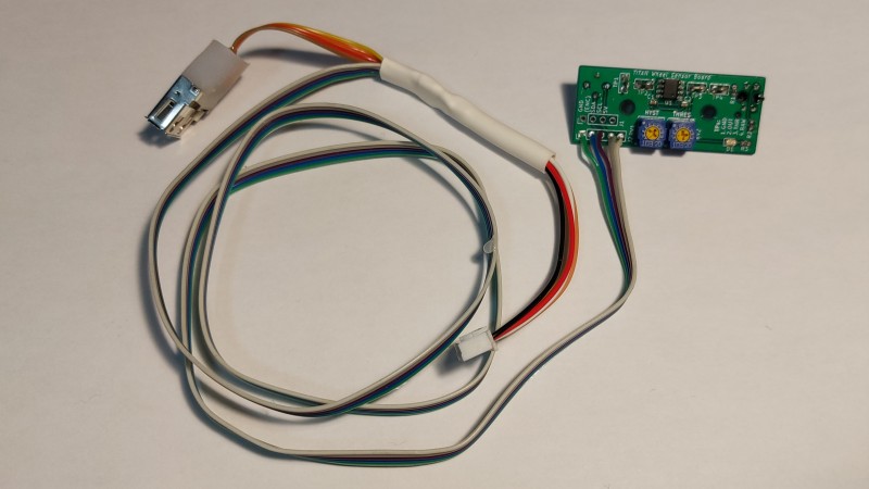
Wheel Board
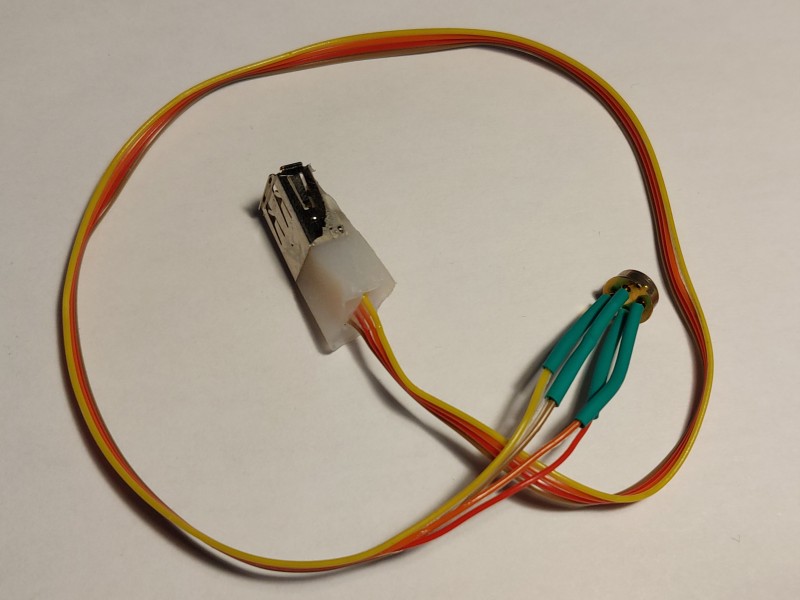
Given the few parts on the daughter board I didn’t purchase a stencil for it and just hand soldered all the parts in place. Although these original photos show the cable harness soldered directly to the board, I eventually replaced that with a JST header to minimize the strain on the wires and allow the board to be easily replaced as needed.
Although I originally designed the wheel board to have a pass through connection for the front thermal sensor, I decided to minimize the length of wire run through TITAN that I would instead use the cable harness to fork the required connections. I prepared a basic USB header to use as a quick connect for the front thermometer since it needed four wires, which I puttied with hot glue to prevent wire fatigue at the joints.
Analog Power
Although not mentioned as part of the design, the entire analog system (camera and display) are both meant to be run off a 12 V supply. The batteries we use in TITAN are LiFePO4 batteries with a nominal voltage of 9.9 V. Although both parts we verified to operate properly at this nominal voltage, if it dipped to around 9.6 V the display would stop working. So to ensure stable operation of the spare screen, a boost regulator was needed to produce the needed 12 V from the batteries. So the Blueshift analog power board was assembled and used for this purpose in TITAN since it was designed exactly for this use.
Assembly into TITAN
Putting the electronics in TITAN took place at the end of August 2022 in the days prior to our initial test runs at Downsview Airport, which themselves were only a couple of weeks prior to WHPSC 2022.
Rewiring
Although the structure was the exact same as it was in 2019, I redid all the wiring with the help of some teammates. This was done so that all the wires would be routed inside the frame (they were taped to the inner surfaces in 2019) as well as to add wiring for the new sensors and improve the existing connection (namely for power). Running wires inside the frame protected them from wear from riders in addition to making the system sleeker.
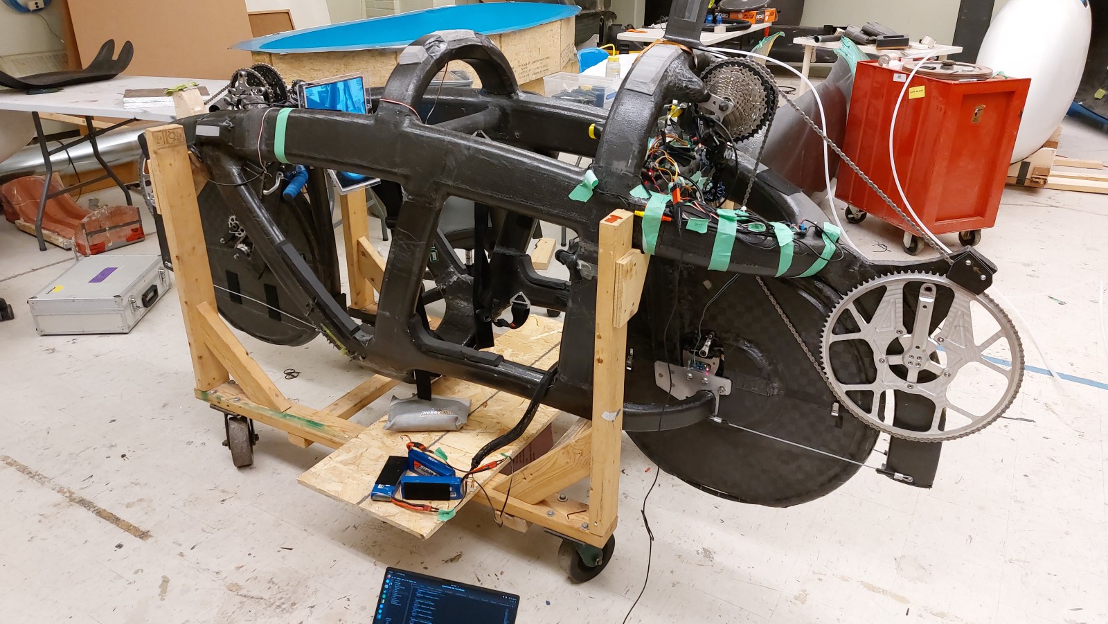
To run wires through the frame a steel washer was tied to a piece of string and a magnet was used to pull the washer along the desired path. Then wires would be tied to the string and pulled back through. In the picture above there is excess wire visible at many of the ports in the frame (front, top, rear) that were later shortened or tucked back into the frame.
While rewiring the entire bike I decided to reposition the front display system electronics to be in the rear. In 2019 the TITAN board, RPi, and display driver board were all nested behind the front screen. This was far from ideal since it needed many wires to be run to front including the ribbon cable for the front camera which was susceptible to noise along the ribbon cable and poor intermediate connections. Moving the RPi and TITAN board to the rear meant that only a power connection and HDMI cable needed to be run from the rear to the front, so the data connection between the two RPis and most sensor was shortened including the camera. Furthermore, by placing the majority of electronics at the rear meant they were accessible from the hatch which made them easier to reach for maintenance without needing to remove the whole fairing.
Mounting Sensors
Once the majority of wiring was in place we mounted the sensors where needed.
- CO2 sensor was placed near the top, between the riders’ heads
- Digital humidity and temperature sensor was placed near the air intake at the bottom
- Front wheel brake thermometer had a hole drilled in the front wheel fairing
- Rear wheel board was mounted inside the wheel bracket
For the front brake temperature sensor cable harness a similar USB connector was prepared to what I did for the wheel harness board. I made sure to repeat the connections that were made then so any off-the-shelf Male-Male USB A cable could connect them.
Mounting the wheel board for the rear wheel was not as easy as expected. Since the board used through hole components and was mounting to metal we needed to add insulation to prevent the terminals shorting through the aluminium. Further spacing material was needed under the board to lift it since it was discovered that the IR reflectometer used as an optical encoder was making contact with the brake disk and actually getting damaged. In the end a popsicle stick under the board was used as our “precision” isolating spacer.
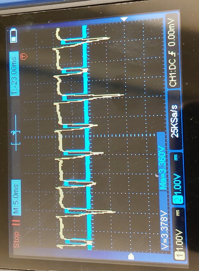
Once installed the rear wheel sensor needed to have the optical encoder circuit tuned. This involved a couple nights of us fiddling with adding retroflective tape to the brake spokes and tuning the trimmer potentiometers on the board for the comparator. It is in this process we also learned about the aforementioned contact wear on the sensor. Nevertheless, in the end we persevered and had some nice, noise free digital signals for the STM32.
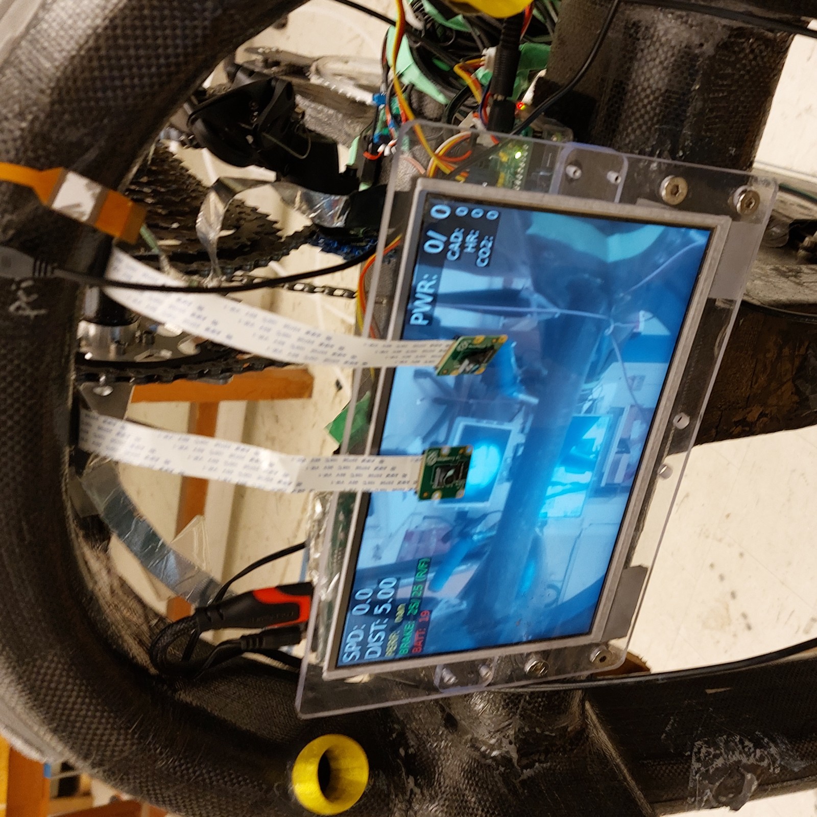
Screen Tests
After installing all the sensors and wiring everything up, a basic functionality test was done on the microcontroller to ensure that it was able to communicate with all the sensors in TITAN and the RPi’s to validate their connectivity and video output. All connections worked as expected!
The front video system is two separate camera feeds on entirely separate display systems, with absolutely no connection between them. The upper screen is the digital camera system as hinted at by the overlay, the lower is the analog camera system. Note: for this the analog camera is inside but not properly seated in the mast so it is partially obscured. This was remedied later prior to WHPSC.
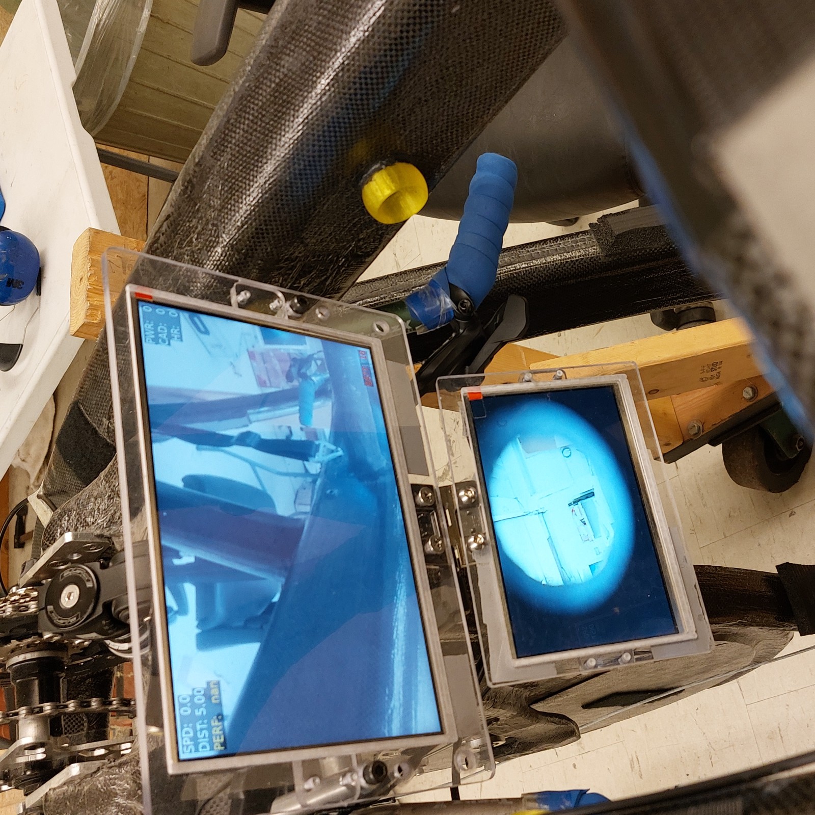
The rear system is only one screen with a front-facing digital camera system. For testing I used lose hanging cameras as shown in front of the screen in the picture below instead of the ones in the mast. Slightly visible behind the screen is the electronics as I was doing initial placementrs.
Coding
Coding TITAN was a bit different to my other projects for HPVDT, since it benefited from the long design cycle for the bike as well as iterating on the work of multiple other projects; the first iteration of itself, Blueshift, and the telemetry project. This greatly sped up development for TITAN in these areas. However there was still much work to be done.
The codebase for TITAN comes in two halves: one set of code for the microcontroller on the main board, the other half being the code running on the RPis. Each half had it’s own challenges that needed to be overcome. Each portion of code could be developed largely independently of one another.
Microcontroller Firmware
Of the two halves of TITAN’s code, the microcontroller code changed the least from 2019 since its purpose was to primarily collect data and most of the sensors were reused. Thanks to the hardware for the 2020 revision of TITAN largely resembling the hardware that went into the final version much of the code for different sensors was validated well before the 2022 hardware was assembled!
As in the previous iteration of TITAN, the main purpose of the microcontroller is to collect the data from the sensors within TITAN and provide said data when requested. However, unlike the last version of TITAN it is also responsible for handling the wireless communications. USB communication/debugging was disabled on TITAN to reduce the program size to fit on the microcontrollers used.
The microcontroller was coded originally in C/C++ using the Arduino IDE with the needed libraries to program STM32s. As the codebase grew it became unwieldy to continue using the Arduino IDE (version 1.8.13 at the time) so I migrated the code to C++ in PlatformIO. This enabled better code organization and many other creature comforts of modern IDEs, it also had the unexpected but appreciated benefit of using a compiler that made my code smaller!
Collecting Sensor Data
The microcontroller is the interface for all the sensors on TITAN, so it needs to collect and process the data from all the sources into a useful form for TITAN (e.g. a voltage reading into a battery level). To recap the sensor selection section the following were used on TITAN, with the last two being additions since 2019.
- Resistor voltage dividers to derive battery levels
- Digital Humidity and Temperature (DHT) (DHT22) to monitor ambient air conditions
- Optical Encoder for wheel-based speed and distance covered
- GPS (Ultimate GPS Module) used for GPS speed and distance, precise location isn’t important to us
- IR Contactless Thermometers (MLX90614) for brake disk temperatures (one for each wheel)
- CO2 Sensor (MH-Z19) for internal atmospheric conditions
The STM32 collects the data off these sensors by periodically polling them in the case of battery levels, brake temperature, humidity, and air temperature, or by processing data as it becomes available for the CO2 sensor, encoder, or GPS. With the exception of the encoder, all of the sensor data streams update less than once a second. This is nice so the microcontroller doesn’t get overwhelmed checking all them and handling the communications with RPis and the radio module.
As part of my refactoring of the TITAN code when I switched to VS Code/PlatformIO I wrote a series of small C++ files for each sensor to make the code related to each easier to read and work on. The result is that all sensors have a setupSensor() and checkSensor() function for them that is then called in the main code loop where needed.
In addition to these basic libraries I prepared for the sensors to set them up and check them, I did make use of several open-source libraries developed for our more complicated sensors like the GPS.
Battery Level Code
Monitoring battery level was coded in the same way it was for TITAN previously: reading the analog value from a resistive divider, calculating the battery voltage, looking up the charge level. For more details check out the battery section for TITAN 2019.
This check is done once every few seconds even if checkBatteries() is called more frequently using the code below. A similar structure is used for the other periodically checked sensors.
void checkBatteries() {
  static unsigned long batteryTime = 0;  // Stores time for next battery check

  // Check if it is time to update battery levels
  if (millis() > batteryTime) {
    FBatt = batteryLevel('f');
    RBatt = batteryLevel('r');

    batteryTime = millis() + batteryPeriod; // Sets next check time
  }
}
Humidity and Temperature Code
This is done using the excellent DHT library from Adafruit which allows the DHT22 to be used in just a few lines of code as per their example. The only real funky business here is that in order to store the temperature and humidity to one unsigned byte I do some math to alter their values before saving them.
void checkHDT() {
  static unsigned long dhtTime = 0;

  // Periodic DHT measurement
  if (millis() > dhtTime) {
    humidity = dht.readHumidity() * 2;            // Humidity reading
    temperature = 50 + dht.readTemperature() * 2; // Temperature reading

    dhtTime = millis() + dhtPeriod; // Sets next measurement time
  }
}
Encoder Code
Although the sensor and circuit used for the encoder has changed since 2019, the interface is still the same: a digital signal that pulses with each rotation of the wheel. This triggers an interrupt in the microcontroller that determines the current rotational period and increments the count of rotations, thus the speed of the bike and the distance it covered can be calculated.
There were two version of this interrupts prepared: one that used the builtin micros() function to track time between pulses and another that used a hardware timer. The timer-based system was meant to address the issue of if the there were competing interrupts delaying the encoder interrupt which would result in a late micros() relative to the actual event occurrence. The timer presented some issues in implementation due to the range of expected pulse periods so it was ultimately not used.
Although the use of an interrupt negates the need for a typical “check” function for the encoder, there is a function to check for if the encoder hasn’t been pulsed for a few seconds implying that the bike has come to a stop called checkEncoderTimeout().
GPS Code
The GPS communicates with the microcontroller by a UART line and makes use of the tinyGPS library by Mikal Hart to parse the data it provides as well as process it for data like distance to a point. Outside wrapping the library code in my own checkGPS() function, not much was done for it code-wise.
Brake Temperature Code
Much like with the DHT22, Adafruit offers a MLX90614 library for these sensors which meant I only needed to prepare a bit of code to properly make use of them.
I did include code as part of setupBrakeThermometers() to blink the status LEDs on the board if either sensor was not detected on boot. This was useful when booting the system after some repairs that might have disturbed their connections, especially for the front sensor since it had a few connectors along its wire.
CO2 Sensor Code
The CO2 sensor outputs the level of CO2 it detects as a 1 Hz pulse width wave, the wider the pulse - the more CO2. So I prepared an interrupt to be executed on any change to measure the width of these pulses and do the math to convert them into a CO2 level.
void CO2change() {
  const bool currentState = digitalRead(CO2Pin);
  const unsigned long currentTime = millis();

  // Used to record previous edge times
  static unsigned long lastCO2Rising = 0;
  static unsigned long lastCO2Falling = 0;

  // Determine edge type based on current state
  if (currentState == HIGH) {
    // Treat it as a rising edge

    // Calculate CO2 level from last pulse
    // CO2 = ppm span * (Th - 2ms) / (Th + Tl - 4ms)

    unsigned long timeHigh = lastCO2Falling - lastCO2Rising;
    unsigned long timeLow = currentTime - lastCO2Falling;

    CO2ppm = CO2Span * (timeHigh - 2);
    CO2ppm = CO2ppm / (timeHigh + timeLow - 4);

    lastCO2Rising = currentTime; // Update rising time
  }
  else {
    // Falling edge
    lastCO2Falling = millis();
  }
}
Unlike the encoder, this interrupt didn’t need any sort of timeout function so once the interrupt is setup on the pin the CO2 sensor doesn’t need any code in the main loop.
Communication with RPis
Communication with the RPis was handled over a dedicated serial line for each. The scheme from TITAN in 2019 was kept but expanded to accommodate the new sensors. This had the RPis sending a message to the STM32, and then the STM32 responds accordingly. The structure of the message received by the STM32 followed this format:
1 character - Message type (capital letters are for sending data, lowercase for requesting data)
1 character - Data length, n (only if the RPi is sending data)
n bytes - Data to STM32 (if the RPi is sending data)
If the RPi is requesting data for itself, it will simply send a lowercase letter for that field, e.g. “s” for speed. If it has data it wants to impart on the STM32 (to pass on to the other RPi), like the ANT+ data, it will start with a capital and be followed by the data length and data itself. E.g. “D!55” would be used to set the rear cadence (D) as “55” which is 2 characters long ("!" has the ASCII code of 33, but I add/subtract 31 to the lengths to keep length characters printable since the first printable character is space, " “, at 32).
When the STM32 is responding with data to a request, it replies with just the data length and data itself (no leading message type character).
Communication with Radio Module
The radio used is an nRF24L01+ module which connects with the STM32 over SPI. For this I used the RF24 library started by TMRh20 which helped me greatly with its examples.
Most of the work needed for this I had already done with my telemetry project, all I needed was to adjust the pin allocations and recompile the code for the STM32 and it worked. In summary, the communications over radio (once the modules are setup) are handled identically to the way the communications are with the RPis, however whereas the RPis communicate over a serial stream with the STM32 the radio messages are each distinct messages/packages. One benefit of the radio messages is that there is an interrupt pin for when complete messages are received which isn’t present with the serial lines.
As I was working and testing the radio communications with our base station I realized that is took tens of milliseconds for each data exchange with TITAN. So for the couple dozen fields of data each individual requested this added up to a notable amount of time on both ends. So I experimented by implementing a single condensed package that was binary encoded (as opposed to the plain text used until now), this allowed much more data to be crammed into a single data packet, I was able to get all the data needed for the base station into a 32 bytes with the usual 2 byte message header this way which allowed it to be sent as a single nRF24 message!
To do this I copied all the data into a custom structure before sending it across the radio. To compress the data, the floating point variables like the speeds were converted to fixed point representation with integers. E.g. 78.921 km/h would be transmitted as 78921 and be divided back when decoded at the receiver.
bulkDataStruct dataLoad;
dataLoad.messageType = '[';
dataLoad.messageLength = sizeof(dataLoad) - 2 + 31;
dataLoad.distGPS = distanceGPS * 1000;
dataLoad.speedEncoder = 1000 * speedEncoder;
dataLoad.speedGPS = 1000 * speedGPS;
dataLoad.rotations = rotationCount;
dataLoad.frontBrakeT = frontBrakeTemp * 100;
dataLoad.rearBrakeT = rearBrakeTemp * 100;
dataLoad.fBatt = FBatt;
dataLoad.rBatt = RBatt;
dataLoad.humid = humidity;
dataLoad.temp = temperature;
dataLoad.CO2 = CO2ppm;
dataLoad.fhr = FHR;
dataLoad.rhr = RHR;
dataLoad.fcad = FCadence;
dataLoad.rcad = RCadence;
dataLoad.fpwr = FPower;
dataLoad.rpwr = RPower;
This approach worked exactly as I had hoped, greatly reducing the communication times which allowed the STM32 to focus on other tasks. This condensed message was later adopted for communication with the RPis as well.
Telemetry Issues
At WHPSC the telemetry worked, but only for short ranges with a clear line of sight. I managed steady connections only up to a range of about 80 m. This meant that our downlink was useless since the chase vehicle it would be in had to stay at least 150 m behind TITAN. At the competition I chalked this up to be an issue of the carbon in the fairing still interfering even with the antenna in the fibreglass section since I managed 600 m with clear line of sight using the same hardware.
Looking back on my code as I write this I realized that I had forgotten to raise the power level above minimum on TITAN’s radio… shoot.
One thing I would potentially change about the radio system it that instead of using it in a call and response fashion, that I would instead simply have TITAN continuously broadcast its status.
Raspberry Pi Code
The code for the RPis departed greatly from 2019. In 2019 the entirety of the RPi code was written in Python, however for 2022 the majority of it was rewritten in C with only some parts in Python. This fundamental rework was done in the interest of improving the reliability and speed of the data overlay system for the video which was the main reason for my previous system being removed in TITAN for WHPSC 2019.
On the RPis there are a few processes going on handed by different bits of code, the flow of it is as follows: on boot there is a python script that is used to determine which RPi it is (front or rear), then execute the requisite programs. These programs being the camera feed, overlay, and ANT data collection if there is an ANT module present. There are also two additional scripts executed by this boot script to monitor and handle button presses on the TITAN boards such as safely shutting down the RPi.
To speedup the boot time of the system as well as making it easier for people to notice errors during boot, I had the RPis configured to boot to command line instead of a graphical user interface. This meant that anything my programs printed would appear in the terminal which occupied the entire screen.
Launcher Script
I prepared one central script in Python that would be executed once the system completed a boot. I named it titan_startup.py was there to then start up the other processes as described since it was easier for me to change the one script then to constantly change the system configuration to launch things on boot.
By using Python I was able to make the script check for an ANT USB receiver which would inform the system if it was the front video system (with ANT USB) or not. Based on this it would launch the appropriate programs and configure the overlay since front and rear riders preferred different layouts.
Button Scripts
I prepared a two small Python scripts to handle the buttons on the TITAN boards.
The “RPi OFF” button was monitored by one script (power_off.py) that would trigger a shutdown of the RPi so power could be safely disconnected without damaging the RPi or the data on the SD card.
When working on TITAN it was annoying to constantly blindly open the terminal and try to terminate the video process after reboots so I made a script to do that for me if I pressed the “RPi ON” button when it was already on called go_to_desktop.py.
Camera Feed
The camera feed was launched by a Python script as it was for TITAN in 2019 since it was the easiest method and worked as we needed it to. By running it as a separate program/process to the overlay it means that should the overlay fail for any reason, the video will continue uninterrupted.
In about a dozen lines the camera feed was up on screen and the video recorded to a file. This code would put the video feed over the entire screen as a “preview”, and start recording it to a fill if desired. The settings we could manage were a stable 720p HD video, at 60 frames per second.
import picamera
import os
from time import sleep
camera = picamera.PiCamera()
camera.resolution = (1280, 720)
camera.framerate = 60

camera.start_preview()

# Get file count to append to video title
videoDir = '/home/pi/Videos'
fileCount = len([name for name in os.listdir(videoDir) if os.path.isfile(os.path.join(videoDir, name))])
print(fileCount)
recordingLocation = "{}/video{:03d}.h264".format(videoDir, fileCount)

camera.start_recording(recordingLocation)
Note: the video file names are numbered to avoid old videos being overwritten.
The recorded videos do occasionally have jumps of a few seconds which I believe is due to a partially incorrect configuration of the recording. This is something that will need to be investigated going forward.
Overlay
The overlay is where I sank most of my efforts into, it is composed of several C files and was originally started following our work on trying a C-based overlay for Blueshift. Although the main function is to put together the overlay, several other parts of code were developed to acquire and log the data needed. In summary it covered:
- Communicating data with the microcontroller
- Drawing the overlay
- Receiving and forwarding the ANT data if applicable
- Logging data to the SD card
- Checking the performance relative to our race simulations
It had a main loop that worked though a setup for all its feature, which were selectively enabled using call parameters. For example bike.bin fsl to run the overlay system for the front rider (the f) with serial communications (s) and log data (l). The main loop’s behaviour would be set to respect these options, for example if there wasn’t serial communications enabled then placeholder data would be used for the overlay. This allowed me to focus on different aspects of the program without needing the entire system present or operational, like if I was just tuning the layout of the overlay for a rider and wanted to show them without needing the system to be connected to sensors.
Drawing the Overlay
Initially with Blueshift the we looked into using some more conventional approaches such as OpenCV to handle both the video feed and drawing the overlay atop it, however these solutions failed to reach 30 frames per second at 720p for the video, so I decided to scrap that approach. Since the Python-script “preview” worked as we wanted I decided to keep that and have the overlay once again rendered over it as a separate process.
Looking around online at other people’s work I found that the Raspberry Pi 3B+’s we were using had an API for their video chip called “VideoCore” which allowed graphics to be drawn directly on the low level video buffer memories. These were a bit primitive given their low level, however they were perfect for what we needed for TITAN since we could output graphics on a layer above the video preview creating the overlay on it.
The way the overlay worked was similar to the way it did with TITAN in 2019, a complete image of the overlay would be rendered, then it would be put in a graphics layer above the video feed. This is different to just updating a “textbox” or “label” in a more conventional UI.
Using the examples included in the library I was able to put text in arbitrary graphics layers as well as basic shapes in a graphics object and push it to a graphics layer. By combining these examples I was able to make some basic functions that would draw textboxes around the screen as I desired so the text would have a slightly transparent background the them to improve legibility.
void renderText (char text[], int x, int y, int size, char foreground[], char background[]) {
      graphics_resource_render_text_ext(overlayImg, x, y,
                                     GRAPHICS_RESOURCE_WIDTH,
                                     GRAPHICS_RESOURCE_HEIGHT,
                                     GRAPHICS_RGBA32(foreground[0],foreground[1],foreground[2],foreground[3]), /* fg */
                                     GRAPHICS_RGBA32(background[0],background[1],background[2],background[3]), /* bg */
                                     text, strlen(text), size);
}

void renderTextAligned(char text[], int x, int y, int size, char foreground[], char background[], char horizontal, char vertical) {
   // Determine the rendered dimensions of text
   uint32_t widthOfText=0, heightOfText=0;
   graphics_resource_text_dimensions_ext(overlayImg, text, strlen(text), &widthOfText, &heightOfText, size);

   // Horizontal Justification
   if ((horizontal == 'c') || (horizontal == 'C')) x = x - (widthOfText / 2);
   else if ((horizontal == 'r') || (horizontal == 'R')) x = x - widthOfText;
   // Otherwise assumes left

   // Vertical Justification
   if ((vertical == 'c') || (vertical == 'C')) y = y - (heightOfText / 2);
   else if ((vertical == 'b') || (vertical == 'B')) y = y - heightOfText;
   // Otherwise assumes the top

   //printf("TEXT SIZE: %d, HEIGHT: %d",size, heightOfText);
   renderText (text, x, y, size, foreground, background);
}
To make the overlays easier to code I then made a series of wrapper functions for these functions so that I would only need to pass the values, then inside these functions it would be formatted into a nice string and the parameters relating to its position and such would be there too so it would be easy to find and tune the overlays to the request of our riders. Below is the code for rendering the speed values (wheel and GPS speed) for the front rider’s overlay.
void renderFSpeed(float speed, float gpsSpeed) {
   char temp[50];
   sprintf(temp, "SPD/GSPD: %4.1f / %4.1f", speed/KM_TO_MI, gpsSpeed/KM_TO_MI);
   renderTextAligned(temp, 10, 10, 30, WHITE, GREY_BG,'l','t');
}
Since I could change the colour of text on the fly the riders requested that some of the text change colour with the value, such as the battery levels. This was done by making a function that would receive a value and then bucket it based on a set of limits and return the appropriate colour.
char *colourByValue(float value, float lower, float upper, char low[], char mid[], char high[]) {
   // Returns a colour based on how the value compares to two limits
   char *resultColour;

   if (value < lower) resultColour = &low[0];
   else if (value > upper) resultColour = &high[0];
   else resultColour = &mid[0];

   return resultColour;
}

void renderFBatteryPercentage(int battPer) {
   char temp[50];
   sprintf(temp, "BATT: %3d", battPer);

   char *colourToUse = colourByValue(battPer, lowerBattLimit, upperBattLimit, RED, YELLOW, GREEN);

   renderTextAligned(temp, 1270, 715, 30, colourToUse, GREY_BG, 'r', 'b');
}
These function calls for each field were then combined into larger wrapper functions for each rider to declutter the main loop.
void updateOverlayFront(float spe, float dist, int pow, int cad, int hr, float perf, float fbrake, int batt, float gpsSpeed) {
   graphics_resource_fill(overlayImg, 0, 0, widthOverlay, heightOverlay, GRAPHICS_RGBA32(0,0,0,0x00));

   renderFSpeed(spe, gpsSpeed);
   renderFPerfPercentage(perf);
   renderFCadence(cad);
   renderFBatteryPercentage(batt);
   renderFPower(pow);
   renderFHR(hr);
   renderFDist(dist);
   renderFBrakeTemp(fbrake);

   graphics_update_displayed_resource(overlayImg, 0, 0, 0, 0);
}
This overlay system was great, it could be updated upwards of 10 times a second! Since it was separate of the video feed, it would not be recorded as part of that footage, so we could make it nicer and re-add it in as we liked if we edited the videos. The major issue with this code is that it is specific to the Raspberry Pi 3B+’s and older, it cannot be compiled as is for newer models or other microcomputers. This is something the team will have to address in the future by moving to more hardware agnostic code.
Communication with the STM32
Communication protocol with the STM32 was outlined in the STM32’s section on this, to handle this I wrote a basic serialComs set of C-code to handle serial communication so it would be easier to use in my main loop.
There are only a few things worth mentioning on the RPi side of things. First is that the RPis block (wait) the program until a response is received following a request. This is why the STM32 doesn’t need to specify what its response is for, the RPi assumes it is for the most recent request sent.
Secondly, I didn’t prepare a nice function to handle the bulk message developed with telemetry in the serialComs files and just have it decoded in its full 80+ lines in the main loop. By adapting this it also greatly improved the update rate of the overlay since each individual request took about 25 ms to process so the overlays were only getting updated at a rate of three times a second, with this bulk message it was brought up to about 10.
Logging
All data from the microcontroller was logged in a CSV file stored on the RPi using code in the logging files I prepared. These simply create a new CSV file for each run and append it with data each time the overlay is updated which isn’t a perfectly regular interval but close enough for our purposes.
Ideally these logs would be labelled with the start time and date for a run, however since the RPis didn’t have real time clocks to keep time when they were off their clocks needed to be regularly synchronized over networks. This wasn’t feasible when launching TITAN in the middle of a highway at WHPSC so I instead used a count of log files to differentiate them. There was ample time for me between runs to extract the logs and name them manually to reflect which one was for which run. I left a simple switch in the code to toggle between these two naming schemes if desired in the future.
Time Trial Code
The timetrail code was used to monitor and report the execution time of portions of code when I was working on reducing the iteration time for the overlay to locate and address bottlenecks. This was a set of code is only used for development.
Race Sim
The team has designed and refined custom simulations over the years to provide us an estimate of a given vehicle’s performance in a certain race given parameters like input power or aerodynamic coefficients. As part of TITAN the lead requested that we try to have some sort of “performance factor” shown to the riders. This performance factor was meant to indicate if the bike was performing better or worse than expected, and thus if we had a better or worse chance at breaking our record that run. Based on this the riders could decide to increase their efforts or conserve them for when conditions were more favourable.
The concept for deriving this performance factor was to compare the present speed of TITAN to what the simulation expected with the power put in and characteristics of the bike/track. The factor would be the percentage the actual speed was of the expected, so if TITAN was a bit faster than expected it would be something like 102% implying favourable race conditions.
I managed to port the most recent simulation from MATLAB to C code and verified that they both produced the same results. However, due to some issues relating to the collection of power data mainly from the front rider (signal issues in TITAN then the fatal failure of their power pedals) this system wasn’t properly tested and used. I do expect it would, had there not been these power issues, but I guess we’ll find out in the future. This is the only code that needs TITAN to be complete to be tested properly.
ANT+
Collecting the biometric data (cadence, heart rate, pedal power) from riders over the ANT+ network was probably my second biggest headache for TITAN after the overlay.
Originally I wanted to write it in C (or C++) to be included as part of the overlay binary. However, the official ANT+ libraries in C for RPis were not playing nicely with me so I decided to take an alternative approach and used a separate Python script to collect the data similarly to how it had been done on TITAN previously.
This script simply tried to connect to the devices in TITAN using the USB and then collected the data of interest from them, printing the most recent values for each in one line, separated by commas, twice a second to the standard output which in most cases is the terminal when launching a program from terminal. This approach allowed me to pipeline the data output from this script into the overlay program on that RPi by calling the two like so: python ./titanant.py | ./bike.bin fcasl.
#Use stdout to pipe data to another process (the display)
stdout.write("%03d,%03d,%03d,%03d,%03d,%03d\n" % (
    front_cur_hr, front_cur_cad, front_cur_pwr,
    rear_cur_hr, rear_cur_cad, rear_cur_pwr))
This pipelining was done not only to put the data on the overlay, but because only one process could write data to the serial line at a time and I didn’t want the two separate processes for ANT and the overlay to fight for communication to the STM32. This meant that the overlay would read the data from the ANT program in its standard input so it could then parse it to get the values it needed both to display and to forward to the STM32 so they could be passed further along to the other RPi or telemetry system. This did require the creation of an antInterface set of C code for the overlay program.
This code worked once I hard-coded the right device IDs for the riders. When trying to get the right IDs for each device and calibrate the length of crankshafts for the pedals at WHPSC, I had more devices appear than expected so I calibrated them all as though they were ours. It turned out that these were the devices of the Italian team that had been doing the same next to us. So I guess that was my first blunder into adversarial electrical work, and I quickly apologized.
As part of our main loop we did have some code with the intent of providing a time average of power for the riders, as opposed to the instantaneous reading. This code was faulty for our first few runs; although it did average the data just fine, it accidentally had it display 0 for both powers instead of the average which caused confusion for the riders at first.
There were some issues with the front pedals which appeared to be from signal loss since they were at the opposite end of TITAN to the ANT+ receiver (in the RPis), although it was soon after found that the pedal had failed mechanically internally so that might have been the main issue.
Outcome
The complete electronics worked to a base level when we arrived at WHPSC which was a first for the team! However, I did tune different parts of the code over the week to iron out some bugs (like the power averaging for ANT) and adjusting different things to the rider’s liking like their overlays. I’d say that about three days into the competition I had ironed out all the bugs and was just working on improvements like bulk radio message. Even with some of the bugs in the data system, the mission critical video feeds all worked without issue in all our runs.
TITAN competed well, however we had unfortunately only ran three official runs due to a crash on our third run, in which neither of the riders were seriously injured. This was likely due to some interference of the front wheel’s fairing causing our front rider to lose control of the steering. It was still a great and fun learning experience for me to represent our team at the WHPSC. We are repairing and improving TITAN and hope to race it again in the future to raise the record we set for tandems with it in 2019!