Blueshift
Table of Contents
Overview
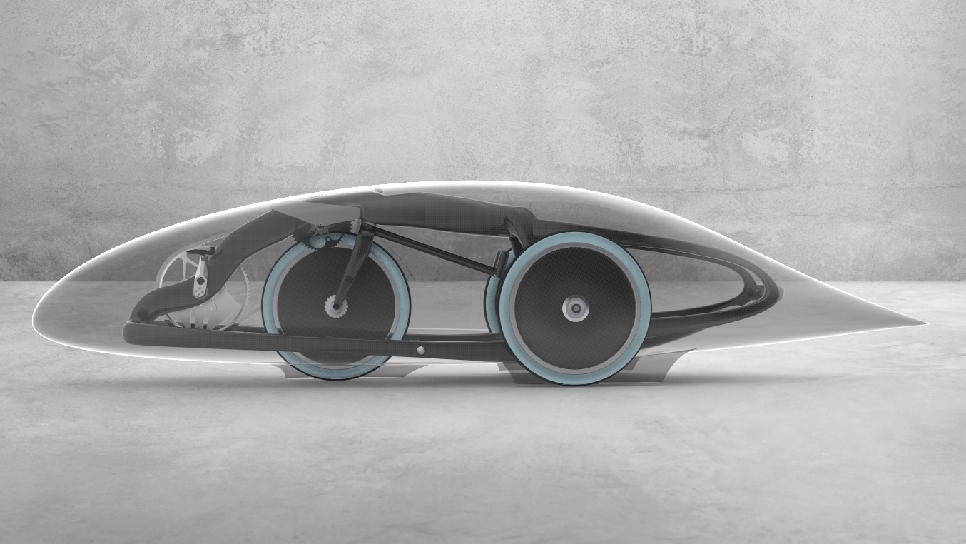
For our team’s entry to the ASME 2020 human powered race event we wanted to try an experimental tricycle layout we had not yet used with the rider fully recumbent between the rear wheels. Since the rider’s vision would be obstructed by both the structure (and their own body even if there was no fairing), this vehicle needed a vision system akin to our speed bikes, the most recent before this project being TITAN, with road worthy features expected of ASME bikes like Zephyr.
As a result this project was largely focused on melding these two projects together and addressing the issues they had, rather than developing new or novel systems. One major difference is the addition of additional viewing angle for the rider although they were meant to be simple.
I lead a team with a few other teammates to develop this system. I focused on the holistic design of the system with the teammates contributed certain components they were interested in working on.
In the end the system was prepared, however due to the COVID-19 pandemic and team decisions that followed; Blueshift was not completed so this system’s true performance will not be known. It did however prove to be a useful exercise for all team members involved with lessons applicable to many future projects for HPVDT.
Requirements
- Provide one front facing video feed, overlaid with vehicle data
- Provide additional views without an overlay:
- Left and right sides (can be “wall-eye” perspective)
- Rear view (can be “wall-eye” perspective)
- Collect the following data to display
- Wheel speed
- Cadence
- Battery level
- Control four sets of lights
- Front
- Rear
- Left/right turning indicators (blink at about 1 Hz)
Objectives
- Gather and relay the following data to the rider
- Rider heart rate
- Ambient temperature and humidity
- Stream data to pit over telemetry
- Record video feed
- Log all collected data
Takeaways
Unit tests are the right way to test systems, especially novel ones. Had I not incrementally tested the power protection systems on their own, I would have likely damaged - if not flat out destroyed the connected modules as I learned they failed to perform as I hoped.
Designing the system as a RPi HAT brought many advantages and should be used for future RPi-based projects (cough cough TITAN)
Made a hypothetical V4 schematic to address the circuit issues and improvements I identified.
Detailed Report
For our team’s entry to the ASME 2020 human powered race event we wanted to try an new tricycle layout for the team that we had not yet used with the rider fully recumbent between the rear wheels. The rider’s vision would be obstructed by both the structure and their own body even if there was no fairing, so this vehicle needed a vision system akin to our speed bikes, the most recent one being TITAN at the time - with road worthy features expected of ASME bikes like Zephyr added, namely the lighting.
There was going to be only one rider in this vehicles, but we wanted to have four views so they would have a better idea of their surrounds than in our speed bikes like TITAN. This is because our speed bikes race in time trials on their own, so we do not need to be worried about any other vehicles around us potentially colliding, so we only concern ourselves with seeing the road before us. For Blueshift, it would be racing concurrently with other vehicles so it would require a much wider field of vision around it for safe and effective operation in races. To this end we wanted one normal front facing camera (like a speed bike), a “wall-eye” camera on each side to check for obstacles, and then one rear-facing camera as well that could also be “wall-eye”.
Overall Design
The basic design of this started by using TITAN as a template; each view would be handled a separate Raspberry Pi (RPi) with their own display and RPi camera. However since all the views would be seen by the same rider, only one needed to be overlaid with data, the front-facing one since it would be their primary display.
Since the other three only needed a video display, and not necessarily a great one either since they were going to be used to check for obstructions, I decided to instead use traditional analog cameras feeding directly into the displays, no middle man. This brought several benefits: lower cost, simpler system both in hardware and software, smaller system volume, and lower power draw. The hardware I bought for this was a set of automotive backup camera displays and wide view drone cameras, both of which worked at 12 V and had analog video interfaces.
This left the main display to be similar to TITAN, or really Eta Prime where there was only one display. This single RPi system would have a board of our that would help it monitor all the relevant information from the vehicle as well as control the lights we needed.
Electrical Design
I had a teammate interested in helping with the project, so I had them prepare a design block for the new light driver circuit I wanted to implement. Other than these blocks, the rest of the circuitry is my own design. The third iteration of the design is what we committed to using in Blueshift.
The design of the board centres on an STM32F103 development board and RPi pair which do all the data collection, fanning out from the STM32 lie all the same sensors used on TITAN (DHT, battery dividers, encoder, etc.), one immediate difference is that the nRF24L01 modulke used for telemetry is connected to the STM32 - not the RPi like in TITAN. On the right of the schematic are the four light line regulators controlled from the STM32. Along the bottom is the power protection circuitry I wanted to introduce and the 5 V regulator.

Microcontroller
The microcontroller used on Blueshift is the STM32F103CBT, mounted to a “Bluepill” development board. This was reused because it performed its duties well on TITAN so I expected it to continue with Blueshift.
It has a wealth of features that make it more suited to this than something like a typical ATmega328P used in our previous projects too. For starters it simply has more pins, which with all the things connected to it is much needed. It has several hardware communication peripherals allowing it to handle two UART-serial lines with the RPi and GPS, in parallel with the SPI needed for the nRF24. Any of its pins can be used as an interrupt which makes connecting lines like for the light buttons or the radio received flag work anywhere.
Sensors
All the sensors from TITAN were reused in Blueshift. The only change was that with only one RPi, the ANT+ dongle used for monitoring rider power and heart rate would be in the main (and only) RPi.
- Resistor voltage dividers
- Battery levels - Used to divide the different battery voltages down to safe levels for the STM32 to measure
- DHT22 (Digital Humidity and Temperature)
- Temperature in vehicle
- Humidity in vehicle
- Optical Encoder
- Wheel-based speed - The period between pulses provides the rotational rate of the wheel
- Wheel-based distance - The number of rotations is counted and used to estimate the distance travelled
- Crank-based cadence - The rate our rider is pedalling
- GPS
- Location - Not super useful during rides but useful in run analysis
- GPS-based speed - A redundant speed value in the event the encoder is not acting correctly
- ANT+ Dongle (USB connection to RPi)
- Cadence - The rider will have ANT+ power pedals that broadcast this
- Power - The rider’s power pedals also broadcast this
- Heart Rates - The rider will wear heart rate monitors that broadcast this
Telemetry
For wireless communication I wanted us to try using nRF24L01 modules. These module are primarily controlled using an SPI interface with two additional digital lines to either enable it, or inform its host that its attention is needed. In Blueshift the module is connected directly to the STM32.
Lighting
The lighting driver circuits were designed by another teammate based on the reference designs for the driver chip I selected, the AP3031 from Diodes Incorporated. These are DC/DC converters that would boost the voltage from the supplied battery voltage to what was needed to drive the LED chains with a constant current.
This current was monitored by measuring the voltage across a feedback resistor and trying to keep it at about 200 mV. So the current was set using the resistor value (\(V/I = R\)). For our brightest lights we needed 1 A, so a 200 mΩ resistor was used, the rest of the lights generally needed only 250 mA so they had resistors of about 800 mΩ. This is why both are present in the schematic, although only the one needed would actually be installed during assembly.
These lighting drivers were controlled by PWM signals from the STM32 which let us dim the lights as we pleased. Thus the rider’s buttons did not directly control the lights. Instead the STM32 would monitor the buttons and adjust the lights as needed. This scheme allowed for the automatic or even remote operation of lights, e.g. turning them all on when starting the system.
In addition to using PWM to dim the lights, we added a potentiometer to dial in the current supplied to the lights if needed by contributing to the feedback signal read by the driving IC.
Power Supply
The lighting system and main display could accept the battery voltage (~10 V) as is, however the data collection side cannot. However, for the sensitive electronics side well-regulated 3.3 V and 5 V lines were needed.
The Raspberry Pi needed 5 V with a potential draw of up to 3 A under load. This high power, needed an efficient conversion so a DC/DC switched mode regulator was used in a buck configuration to step down the voltage from the battery. The system I implemented on the board claimed efficiency of over 85% given our input voltage and output load.
To provide the 3.3 V for the majority of the board, I used the 3.3 V generated by the RPi. This made my circuit simpler since I didn’t need to include a dedicated 3.3 V regulator but also prevented any issues arising from a potential 3.3 V mismatch between my board and the RPi that could ruin one or the other.
Power Protection
One minor theme present in this system is power protection. There is the obvious input protection systems for reversed polarity or over-voltage, both of which can damage the system. I added an under voltage stage that would prevent the system from over discharging and damaging a battery. All these systems had designated LEDs to inform the user of a failure, as well as fourth “OK” LED to let users know everything was all correct.
- Reverse polarity protection was achieved using a P-channel MOSFET. If the polarity was correct then the body diode would allow some current, which would then set the MOSFET into it’s conductive, and then saturated state. Much more efficient than a simple diode.
- Over voltage protection was achieved using two P-channel MOSFETs. As the voltage would rise about the threshold set by the Zener D8, the first MOSFET would begin conducting, this would raise the the gate voltage of the second MOSFET and eventually cut off the current to the rest of the system.
- Under voltage protection was achieved using a reference voltage and a comparator. If the voltage fell below some threshold set relative to the reference voltage generated by Zener D6, the main voltage regulator would be disabled.
Once the power passed through these stages, it would reach the system supplying the lights, RPi, and main display!
These weren’t the only protection circuits present through the system though. There were five pairs of protection diodes spread around the circuit (D1 to D5) to limit the voltage at certain nodes to fall between the power rails. These were meant to prevent a failure from the STM32 prom propagating along the data lines to the RPi and GPS leading to them also getting damaged, as had happened with one RPi used for development purposes of other systems before work on Blueshift started.
Analog System Power
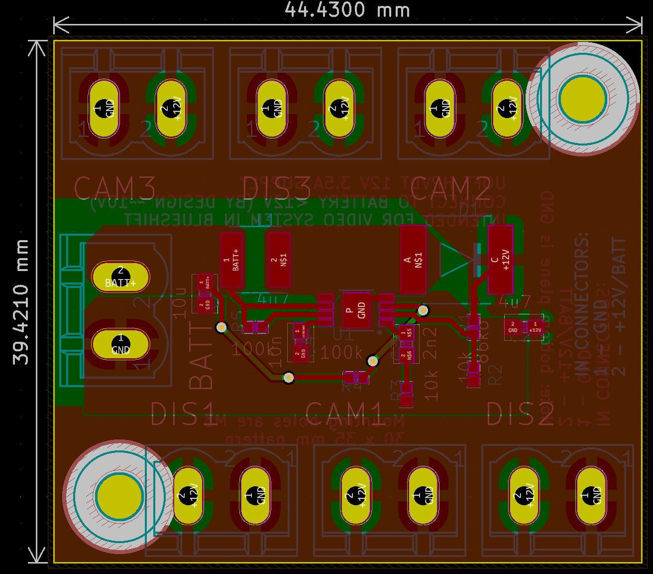
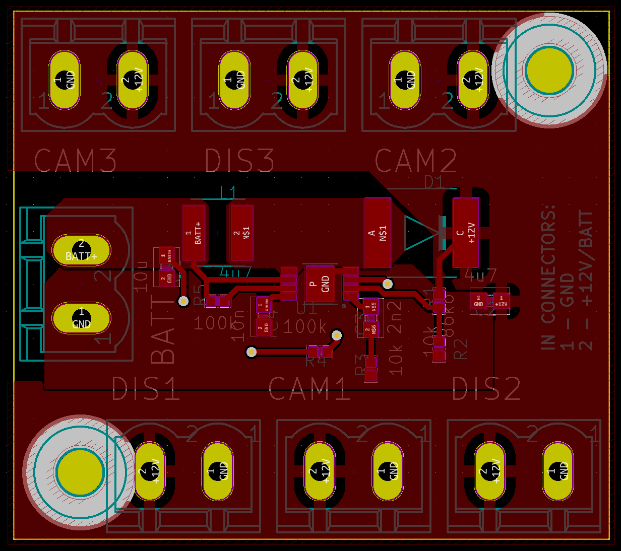
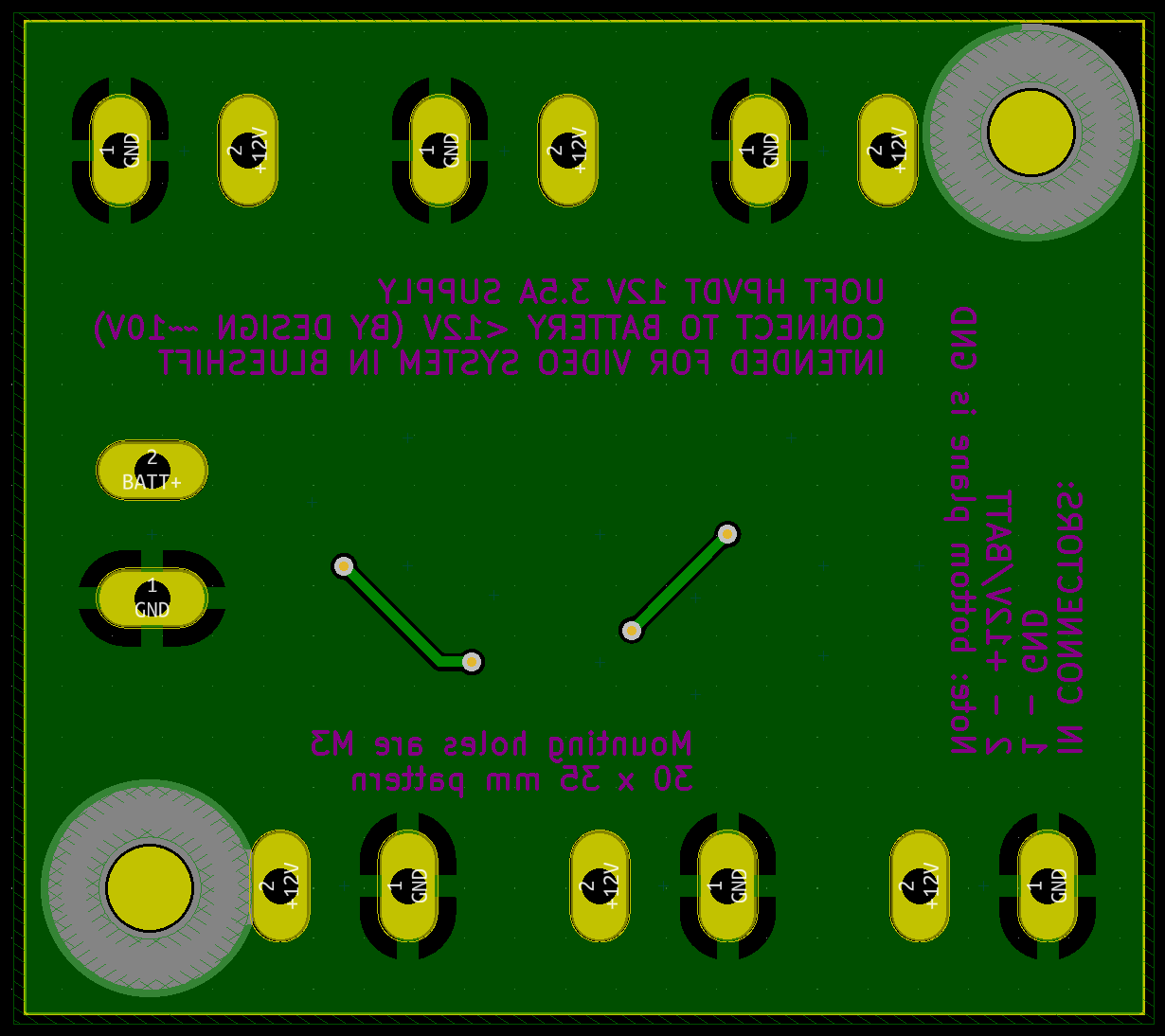
Other than the main Blueshift board there was a 12 V regulator we designed to supply steady power to all three peripheral video systems. It was a simple board, using the reference design for a boost regulator to generate 12 V from our battery’s nominal 10 V. Other than this regulator, there were only the connectors for each of the three cameras and displays to connect to and the battery to feed it.

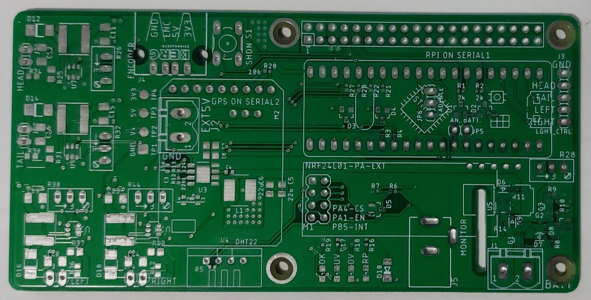
Layout
Note: the boards were originally laid out in EAGLE, they were imported into KiCad to generate these figures. So there may be some small oddities present.
My teammate had prepared the layout for the light drivers as part of her work to make the design blocks for them. Other than those, the rest of the layout I did myself.
The main thing to note with the layout of this system is that it was designed to be a RPi HAT (Hardware Added on Top), that would be seated directly on top of the RPi instead of connected by a ribbon cable to the RPi like TITAN V1 was. This was better because it decreased the footprint the system would occupy, as well as preventing potentially incorrect connections related to the use of a ribbon cable.
There is no general “flow” to the board, instead it is segmented by purpose. In the top right quadrant is where all the data processing occurs between the RPi and STM32 Bluepill. Beneath it, in the bottom right quadrant lie the nRF24 module and the power protection circuitry. To the left of the centre is where the main 5 V regulator was, with the GPS module hanging over it. On the extreme left is where the LED drivers were.
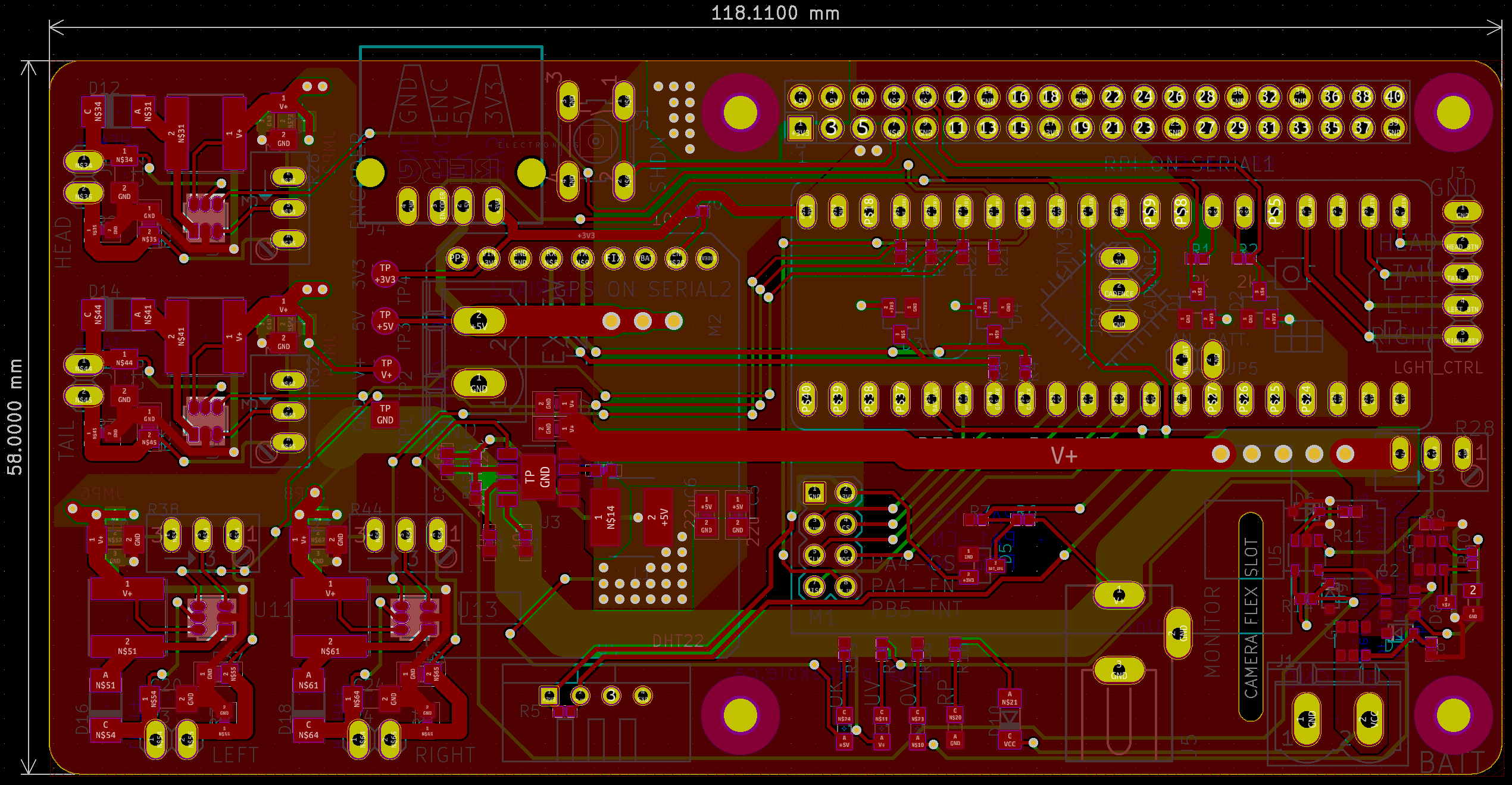
All the parts were mounted to the top of the board.
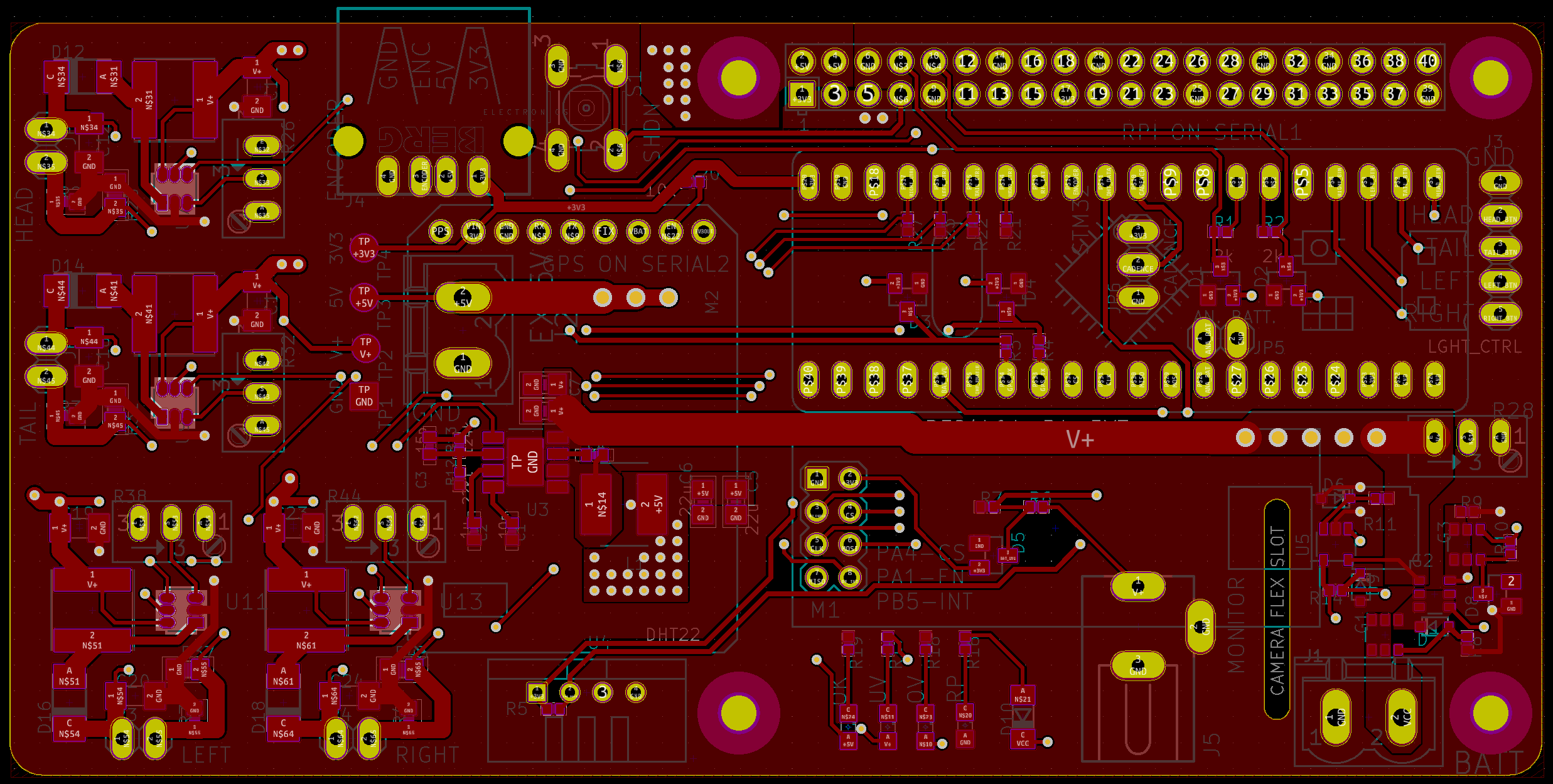
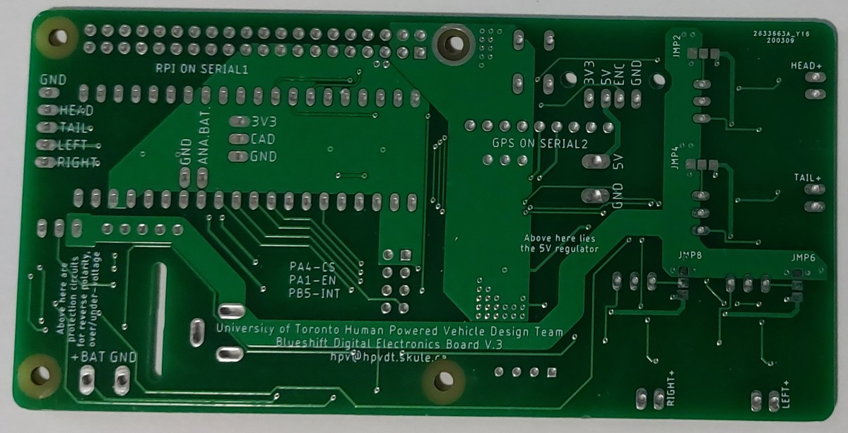
The bottom is devoid of any parts, although I did make use of it to put notes related to the project on the silkscreen that was printed.
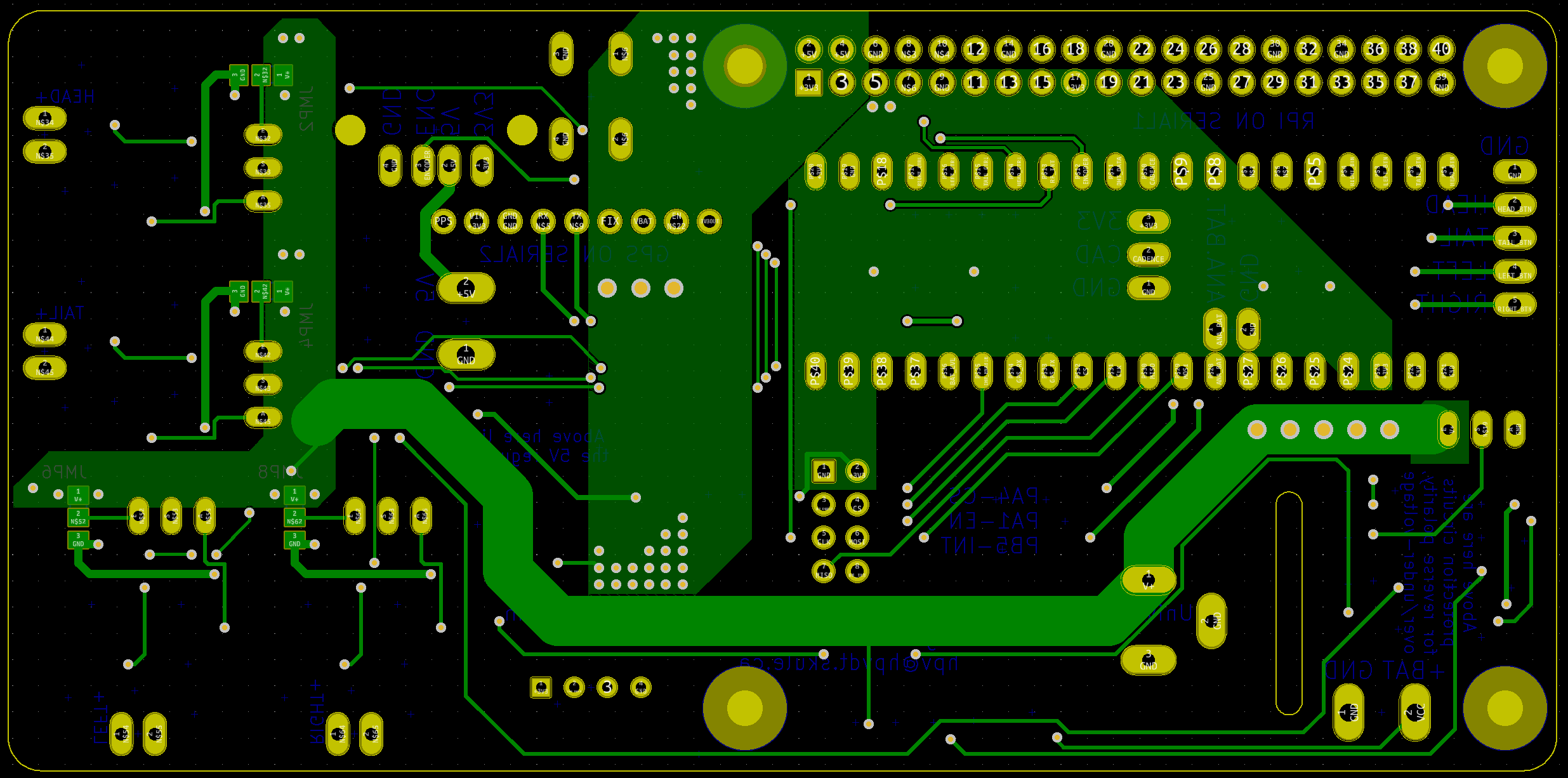
I feel that this board is approaching the limit of complexity I can afford with only two layers. I need to get better or I will need to start making my boards larger to fit the traces I need should I want to avoid going to four-layer boards.
Analog System Board
Given the simple circuit this was a small and simple board to layout and I did it myself.
Assembly
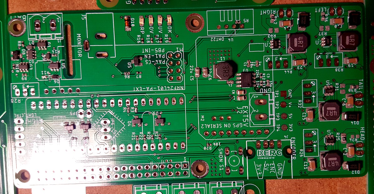
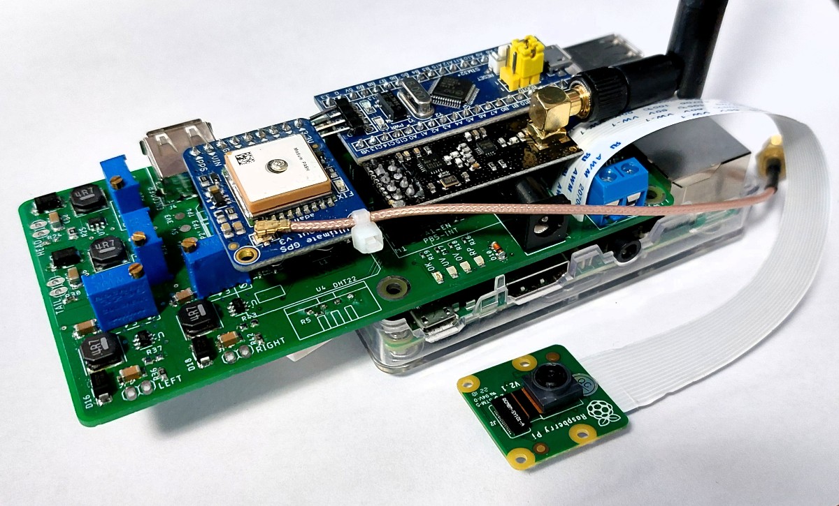
I did the assembly myself, a pretty standard mixed technology assembly. I would like to take a moment to admire what were up to this point my most complicated and interesting board I laid out.
For once I actually stopped to take a picture partway through to show what the board looks like when parts are placed but are not soldered yet.
In the end the board came out nicely as shown in the figures that follow.
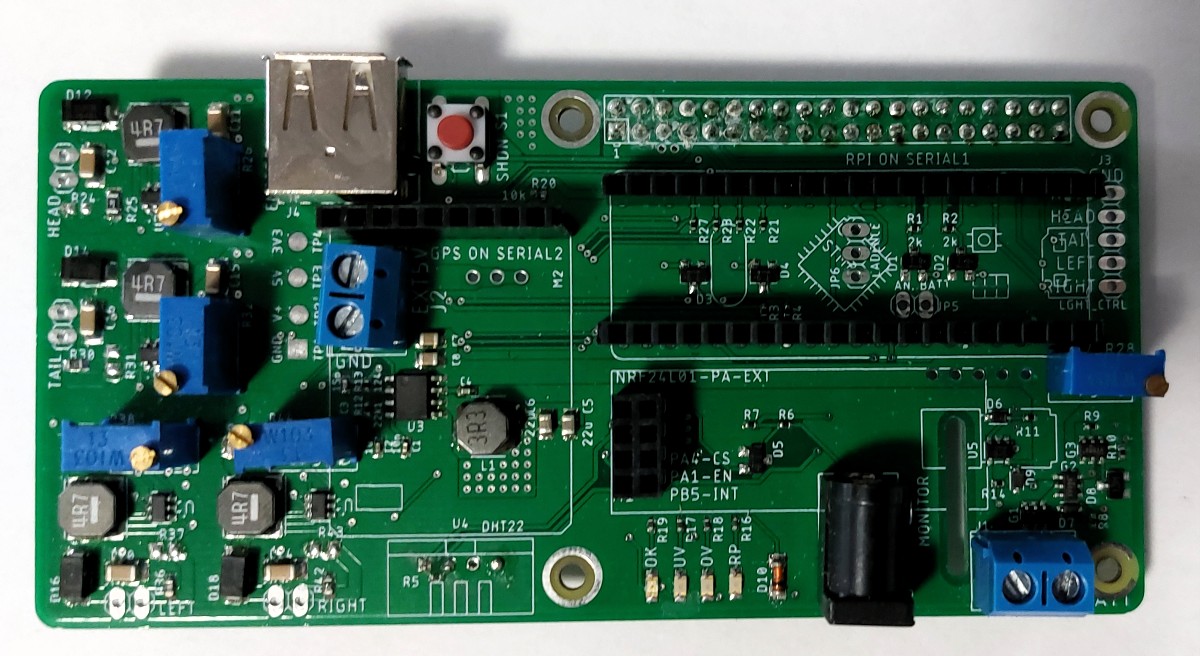
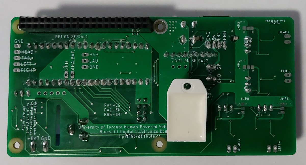
With all the modules mounted to it, and the board seated on the RPi with the camera cable coming through it looks like quite the little system. Would probably introduce me to some new friends if I tried to take it on an airplane.
Assembling the Analog Power
I ordered the parts for the analog video power board, however I never assembled one since it wasn’t going to be used and had essentially no utility for the team outside of its purpose to power the analog cameras and displays.
Testing
Once assembled I put the system through some basic hardware tests before we could begin programming to ensure everything was working as anticipated. If not, there would be a chance the board would fail when finally put into use wasting our time.
To ensure the safety of the board and the modules that would eventually connect to it, the board was tested incrementally. At first with nothing connected to it to test the hardware built into it, then once I was confident I would gradually introduce modules until I had the whole system there.
Power Monitoring Tests
The first tests I did were with the board’s power protection and supply system to ensure they worked. I followed it through the steps below which corresponded to the faith I had in the system operating properly in each condition, ranked highest to lowest faith.
- Normal conditions. Supplied the expected 10V. The system generated the proper 5 V and no error LEDs lit up. Good.
- Under voltage. Supplied 8 V. The “UV” LED lit up and the 5 V supply was disabled. Good.
- Reverse polarity. Supplied -10 V. The “RP” LED lit up and no power made it to the system. Good.
- Over voltage. Supplied 15 V. No error LEDs lit up, power reaching the system, 5 V supply operating. Bad.
- Note: 15 V was still tolerated by all parts present during this test so no damage occurred other.
Looking at my schematic I identified the problem. When I was placing the MOSFET on the power line (G2) I had copied and pasted the MOSFET used for reverse polarity (G1). I had forgotten that it was placed “in-reverse” for reverse polarity protection and left it. This meant that as long as the polarity of the system was correct the MOSFET would conduct either through its body diode or normal means, so it was unable to cut power to the system.
I noted the failure of the over voltage system down for correction in a future revision. I also realized that my under voltage protection system was naive, since it only disabled the 5 V supply (turning off the data collection circuitry) but there was still power on the rail for the main display and lights to still use which could drain or kill the battery. To remedy this, I would have the comparator cut power into the system using a MOSFET as I had done with the other two stages.
Neither of these issues would prevent the system from operating under normal conditions as established with test 1, so I simply made a note to make sure we were diligent about the batteries we used and changed them regularly.
Lighting Tests
Testing the lighting was pretty simple, I soldered a chain of high power LEDs to the output I wanted to test and then used jumper wires in place of the STM32 to send an enable signal to that line. My tests for each line had these steps:
- Normal operation. Have the LEDs soldered to the output, enable the driver with a jumper wire.
- Current check. Use a current clamp around the LED leads to verify the current matches expectations
- Disconnected test. Disconnect the LEDs and enable the driver for 20 seconds.
- Normal operation. Reconnect the LEDs and run them to make sure the driver detected the open load in the previous step and did not damage itself.
All four lighting lines passed these tests without issue.
Data System Tests
Once all the power circuits were tested, I installed the STM32 and RPi had them perform basic data exchanges like on TITAN to check they were communicating properly. They communicated without issue, passing my dummy data back and forth.
After communication was established, I added the sensor modules and ran simple code on the STM32 to check it was able to collect all the data correctly, which it did. It was able to collect GPS and DHT data, pick up on button presses, and catch encoder interrupts.
The final piece that needed to fall into place was the nRF24L01 communication module. I placed it in its socket and had the STM32 run some basic configuration instructions on it and then verify if they were accepted. This proved the nRF24L01 was responsive to the STM32 and was ready to be used.
The system was ready to get coded.
Programming
Although much of the code was reused from TITAN, there were some changes and some novel code that needed to be written specifically for Blueshift. As with TITAN, the code running on the microcontroller was written in C/C++ using the Arduino platform, while the code that ran on the RPi was written in Python.
The main changes to the code of Blueshift compared to TITAN was with the code meant to run on the Raspberry Pi. I was ready to simply reuse my code from TITAN written in Python with the necessary changes made to get it to work for Blueshift. However I had two teammates express an interest in trying to optimize my code and port it to C or C++ in hopes of even better performance that just optimized Python.
Data Collection
Data collection was kept the same from TITAN since we were using all the same sensors. The only changes were that a couple of the pin allocations were changed so that had to be reflected in the code. In summary from TITAN:
- GPS - Used a library
- DHT - Used a library
- Encoders (wheel and crank) - Used interrupts to record their rotational periods/speeds and number of rotations
- Battery levels - Used internal analog to digital converter on STM32 to determine battery voltage and thus level
- Refer to TITAN’s section on this for more detail
Light Control
Light control was handed by a teammate that was interested in contributing some code to the project based on the exercises I had prepared for them earlier in the year. All light control code was on the STM32.
The lights were controlled by PWM outputs so they could be dimmed, with simple analogWrite functions used for this.
To capture the rider’s inputs from the buttons, I asked them to prepare an interrupt based system. This system also required software debouncing, to not catch any unnecessary of toggles with each press.
Finally, I had them add new commands to the established data exchange structure so we could both query or set the lights using data commands instead of only the buttons. This allowed us to display the light state on the screen to the rider, as well enabling the possibility of remote control with telemetry.
Data Exchange
This again was taken basically whole from my work on TITAN. Communication between the RPi and STM32 was done over a serial line using predefined message structures, explained below.
1 character - Message type (capital letters are for sending data, lowercase for requesting data)
1 character - Data length, n (only if the RPi is sending data)
n bytes - Data to STM32 (if the RPi is sending data)
As hinted by the structure, the STM32 would only receive data from the RPi and never initiate an exchange itself. When the STM32 is responding with data to a request, it replies with just the data length and data itself (no leading message type character).
The reason I used a data length character as part of messages, rather than a fixed length or delimiting character to communicate message length is because it allows for greater flexibility than a fixed length, and it doesn’t risk a delimiting character randomly occurring in exchanged data, misleading the RPi or STM32.
ANT+ Data Collection
Just like on TITAN a USB receiver for ANT+ signals was used on the RPi to collect the power, cadence, and heart rate data for the rider. I reused the python code from TITAN, although I trimmed it down to only monitor one set of rider devices rather than two. The RPi would still update the STM32 with this information as it got updated should telemetry be achieved.
My teammates were unable to get a C/C++ version of ANT+ operational, so the Python version was kept for competition.
Video Display and Overlay
The code for this was also copied from TITAN and was essentially the same, just that I removed the different “front” or “rear” code since there was only going to be one rider and display for this so it was redundant. The feed shown to the rider was still a “preview” of the RPi camera with a data-loaded heads up display overlaid.
Although my teammates had come success with putting up a video feed with C-based code using OpenCV, there was a noticeable latency and decreased frame rate compared to my original Python-based approach, which only got worse when they applied an overlay to it. So this was scrapped and we intended to keep the Python video system for Blueshift at competition.
I did keep working on this myself after the cancellation of the competition in the wake of the pandemic, in parallel with my work on the telemetry system. I was able to get a hybrid approach to work where Python code would still be used to put the camera feed on screen as a “preview”, however I used a separate C program to overlay the data using low level graphics functions specific to the Raspberry Pi 3B+s we had. It is this code that is running in the Blueshift telemetry demo video.
Telemetry
Over the year leading up to Blueshift I had been doing some research into how we could finally achieve telemetry with the nRF24 modules I had purchased. I have a telemetry page dedicated to my work on it, so I will summarize it by stating I was greatly helped by the libraries available for it, and that I made functions to easily exchange data wirelessly like it was data flowing between microcontroller/processors on TITAN and Blueshift.
I am not certain I would have had it in time for the competition, but Blueshift would be able to race even without it.
I have a video of me using the system to test my C-based overlay by feeding the system data wirelessly from my laptop.
Note: I forgot to mention in the video but the reason the overlay appears undersized is because it is designed to be put over a 720p video feed, which is the resolution used in the vehicle. However for testing the camera was outputting 1080p to match my monitor’s resolution.
Outcome
Unfortunately near the end of the project just weeks before the competition, the COVID-19 pandemic began so the team had to halt the construction of the bike as we lost access to our campus facilities. (I was able to continue work on this since I was using my own tools and ordering everything to my address anyways). This was soon followed by the cancellation of the event.
After a change of leadership in the team, it was decided that we would not invest the time and resources into competing in ASME’s competitions for the near future to instead focus on our projects aimed at breaking records instead. This meant that Blueshift was not going to be completed, and thus my system would never get to be tested or used properly.
Even so, it served as an excellent design exercise and let me figure out some things to bring to TITAN, notably with layout.
Version 4?
I went back and prepared a new schematic to remedy most of my issues with the design of V3. The issues addressed were:
- Incorrect configuration of the over voltage MOSFET
- I have the under voltage protection system cut power to the entire system using a MOSFET, not just disable the 5 V regulator.
- This will prevent the display or lights from continuing to drain the battery if under voltage occurs.
- Moved the voltage divider for the auxiliary battery on board
- Added protection diodes for axillary battery level line

Although this wouldn’t be made, I still made this since when someone would look back on this project, be it myself or someone else - I would like this to be the schematic they draw from rather than the real but incorrect Blueshift schematic used.