Composite Oven Control System
Table of Contents
Overview
To properly cure most composites our team uses properly, a two step heating process is needed with a controlled temperature ramp between each stage. Most commercial oven controllers are designed to maintain a single constant temperature, so I made one specifically for the team.
This has been in worked on for a couple of years and this system is the third and hopefully last incarnation the team needs. It was designed to fit inside a repurposed case and use screw terminals to connect to power, the heater, and a thermocouple for feedback. Inside the case is the screen for the user to interact with using the number pad on the outside.
The system essentially works, however due to some odd connectivity issues the temperature cannot be read using the current board design and a new board is needed to change the connections between the MAX6675 IC and the ATmega328P. Other than that the software is working properly.
Once I get the new board and assemble it (and the team gets a working heater to control) I will be able to do proper tests to verify the system’s functionality.
Requirements
- Monitor and maintain temperature to a target
- Allow users to input custom parameters for the temperature profile
- Contain everything needed inside one enclosure
Objectives
- Convey to the user the present status of the curing
Takeaways
Some errors just seem to defy explanation. This MAX6675 seems to poison SPI buses, and only works with GPIO bit-banging, not proper SPI buses. No clue why, but I guess I just have to deal with it.
Detailed Report
HPVDT uses a lot of composites in all its projects. These composites have their shape held by epoxy, which we generally leave to cure at room temperature under vacuum conditions. For peak structural performance, and pre-pregnated composites a properly controlled heated curing or “bake” is required. This bake generally has two stages, defined by the following properties:
- Target temperature - How hot to keep it. Generally between 70 and 130 degrees Celsius.
- Hold time - how long to maintain this temperature.
- Rise rate - how fast to heat up the composite to reach the temperature. Typically a couple degrees a minute.
The problem for the team is that most (cheap) oven controller available commercially are designed to maintain a single temperature for a given amount of time. They do not care about the rise rate, nor can they do two stages. So I have been working on making a custom one for the last couple of years.
The software has largely remained the same since the first version, only adapting to the hardware changes between versions. Even the circuitry hasn’t changed much, most of my work has gone into simply making the circuitry better suited to the production environment by fitting it inside enclosures and using proper printed circuit boards.
Needless to say, we’ve come a long way from my first machined board which had an Arduino plug in and used some thermistors. At least I used nice headers for them, mostly.
A loooooong way.
Circuit Design
The heart of the system is essentially an Arduino Nano, since this is what I developed the previous systems for and it also has just the right amount of I/O and features needed for this project. It has headers to allow it to be programmed using either SPI or serial with a bootloader.
User Interface
This was one of my first projects that was intended to be used by someone other than myself, and likely those that would not be thoroughly trained on how to use it, so making a simple user experience was necessary.
User input is handled by a simple 4 x 4 button pad, allowing them to use 10 buttons for entering digits, a decimal point, a backspace key, and then the last four to navigate up, down, left, and right through the menus. The main output to the user is a 20 by 4 character LCD display which uses a series of descriptive menus/forms to allow the user to set the oven’s behaviour and then progress.
Temperature Monitoring and Control
In my earliest iterations I had intended to use NTC thermistors to monitor temperature. However these proved to be very unreliable and inaccurate at the higher end of our temperature range as they approached their rated limits. For this reason I wanted us to move to using a a thermocouple system with an IC specifically to handle the analog to digital conversion for me. In the end I settled on using the familiar MAX6675 IC to monitor temperature with a K-type thermocouple, allowing us to monitor temperatures between 0 and 1024 degrees Celsius to within 0.25 degrees!
To control the heater I used a commercial solid state relay to cut or provide power to the heater. This wouldn’t really allow me to implement some high-end PWM modulation of the heater but it was certainly enough for what we were trying to do. All it needed from the microcontroller is a simple on/off digital signal.
The Resulting Schematic
Combining all these parts into one schematic produces this. Note that I have added connections for a USB charger to provide the system 5 VDC from 120 VAC, as well as a grounding connection for the metal enclosure used.

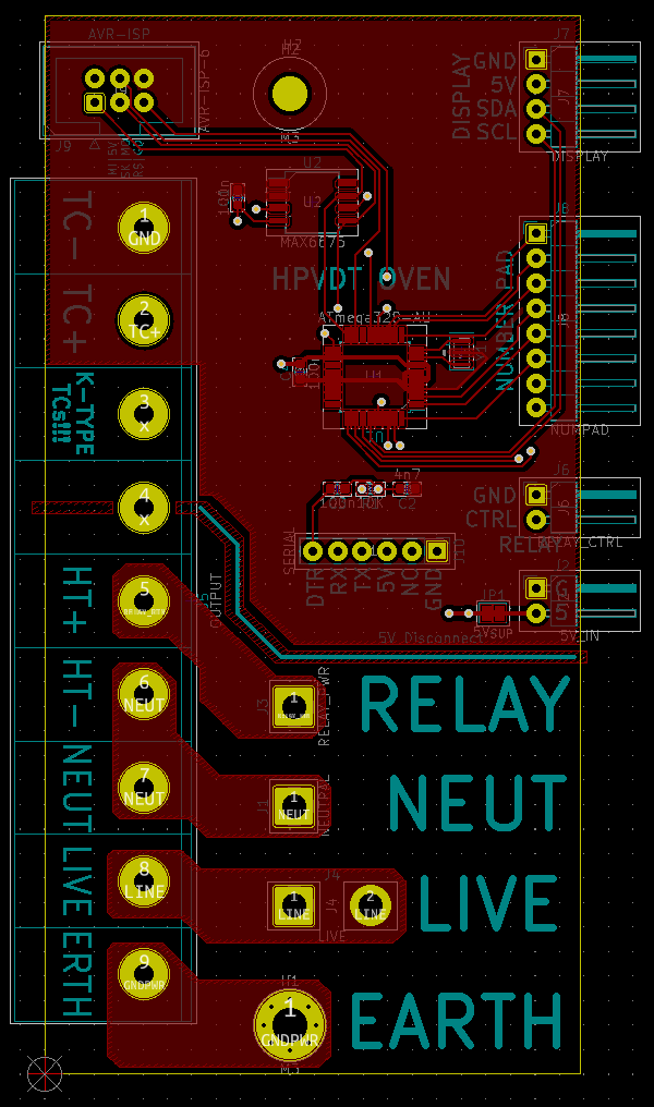
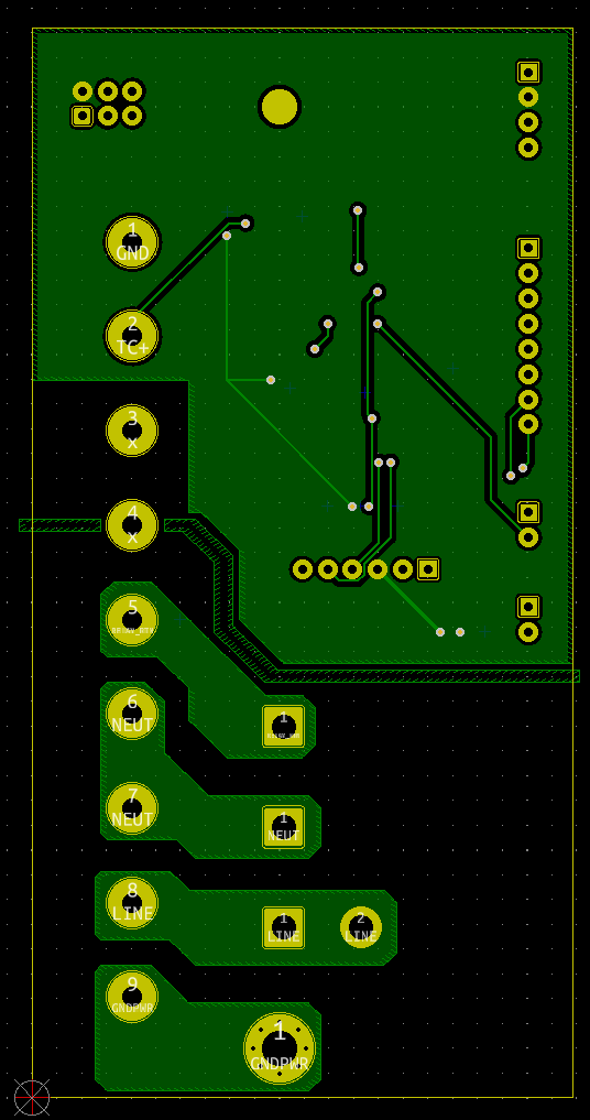
Layout
This board was pretty simple to layout thanks to the rather simple circuit. However this board had to fit inside the enclosure so I made sure to place the mounting holes and edges first before I began laying out my components, lest I be forced to relocate them later.
This was my first time designing a board to have 120V running on it, which was honestly a little frightening at first since I was worried about trace spacing, and other potential issues like accidental shorts in assembly. I kept these high voltage traces in their own region of the board, clearly indicated and segregated from the low-voltage control system.
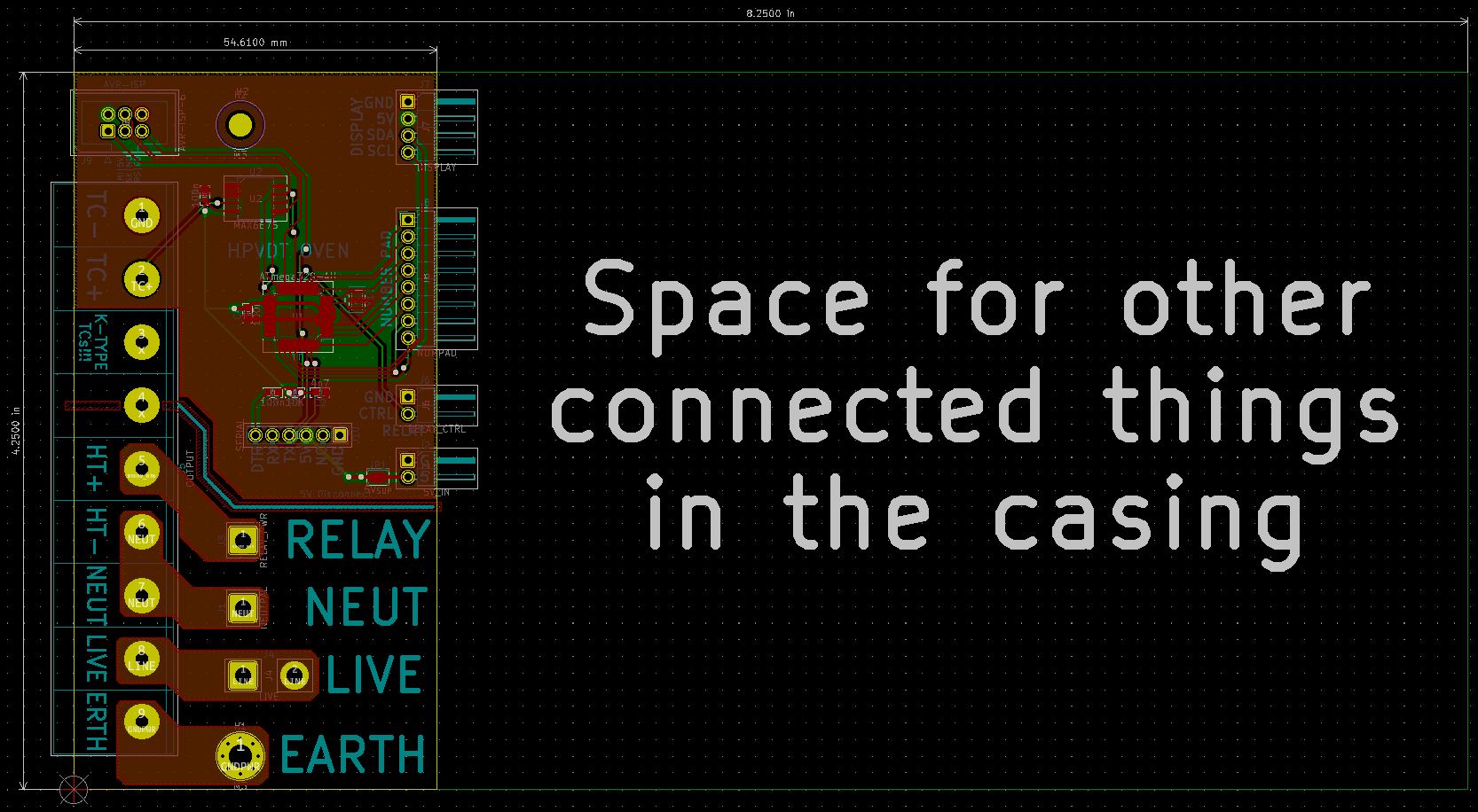
Since these 120V lines would be carrying lots of current to the heater I used large pours on both sides for all 120V lines. I also marked the division between the 120V and control regions with silkscreen lines and a keepout zone for all copper.
Assembly
Unlike most of my other projects where assembly starts and ends with the circuit board, this one had me integrate not only external (off-board) components but also fit them all sensibly within an enclosure. The there was little to actually solder on the board itself in terms of components: four capacitors, two ICs, a resistor, and a resonator - only eight (8!) parts!
Well, eight if we exclude the headers and wires that directly solder to the board but still.
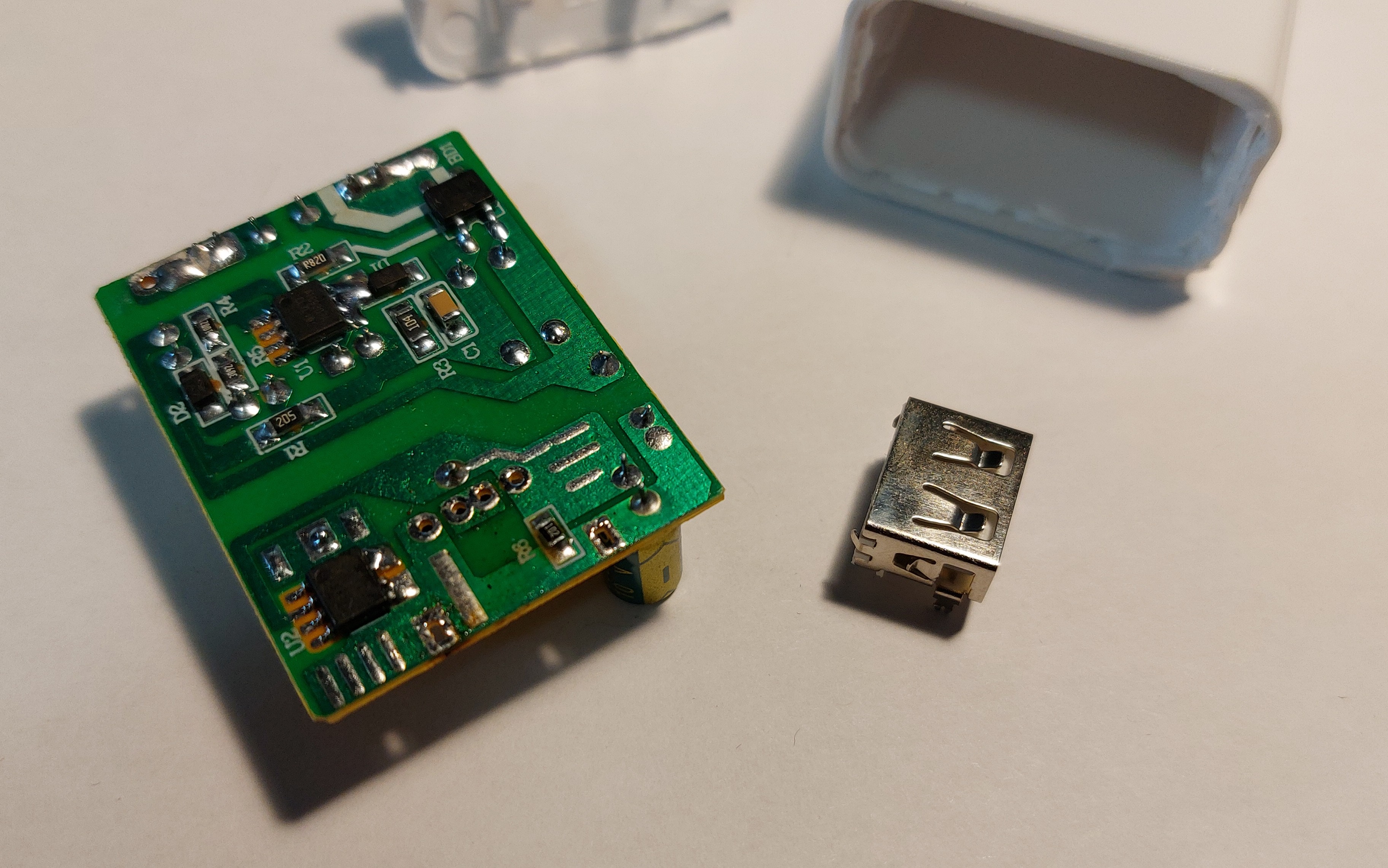
Starting with the external/off-board modules, to provide 5 V to the board I modified a standard USB wall plug to supply 5 V to some wires soldered to it directly rather than butchering a USB cable that may come loose inside the enclosure as it is rattled about.
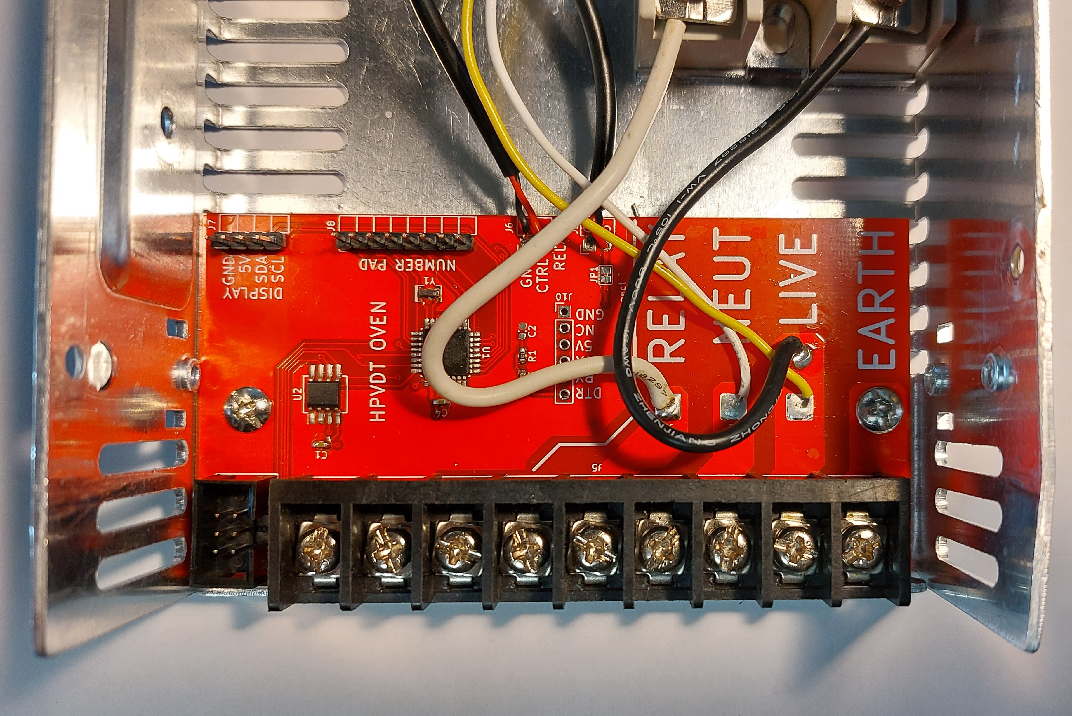
I installed that after re-assembling the charger, as well as the relay for the heater. For all the 120 V lines I checked the insulation rating of my wires and they were all 600 V so this will be safe. I also used heat shrink to cover the charger terminals. In the picture below I have the parts in their final places, however I forgot to take a photo after I secured them down with zip ties.
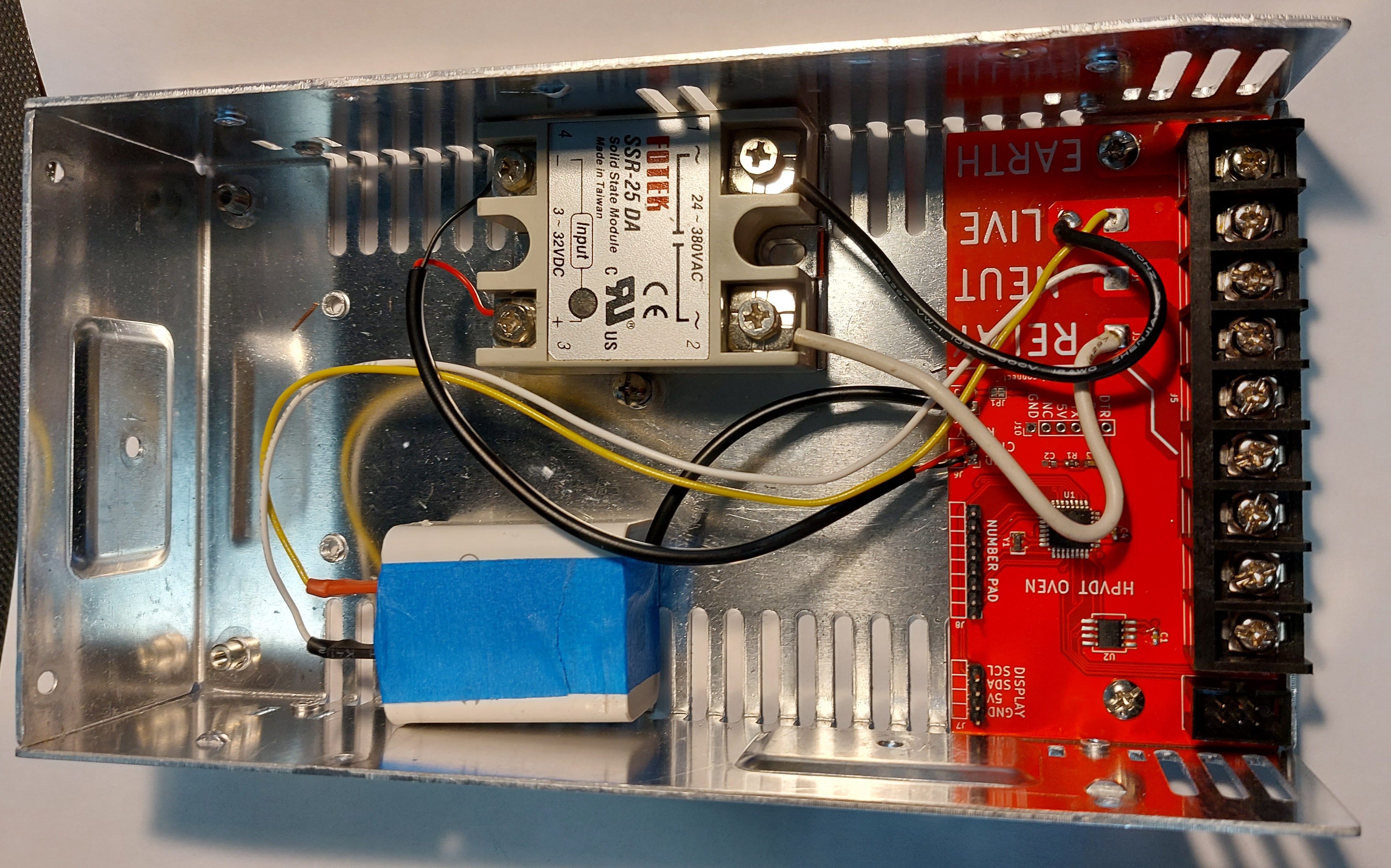
I then connected the display and number pad using ribbon cables to their respective headers and closed it shut.
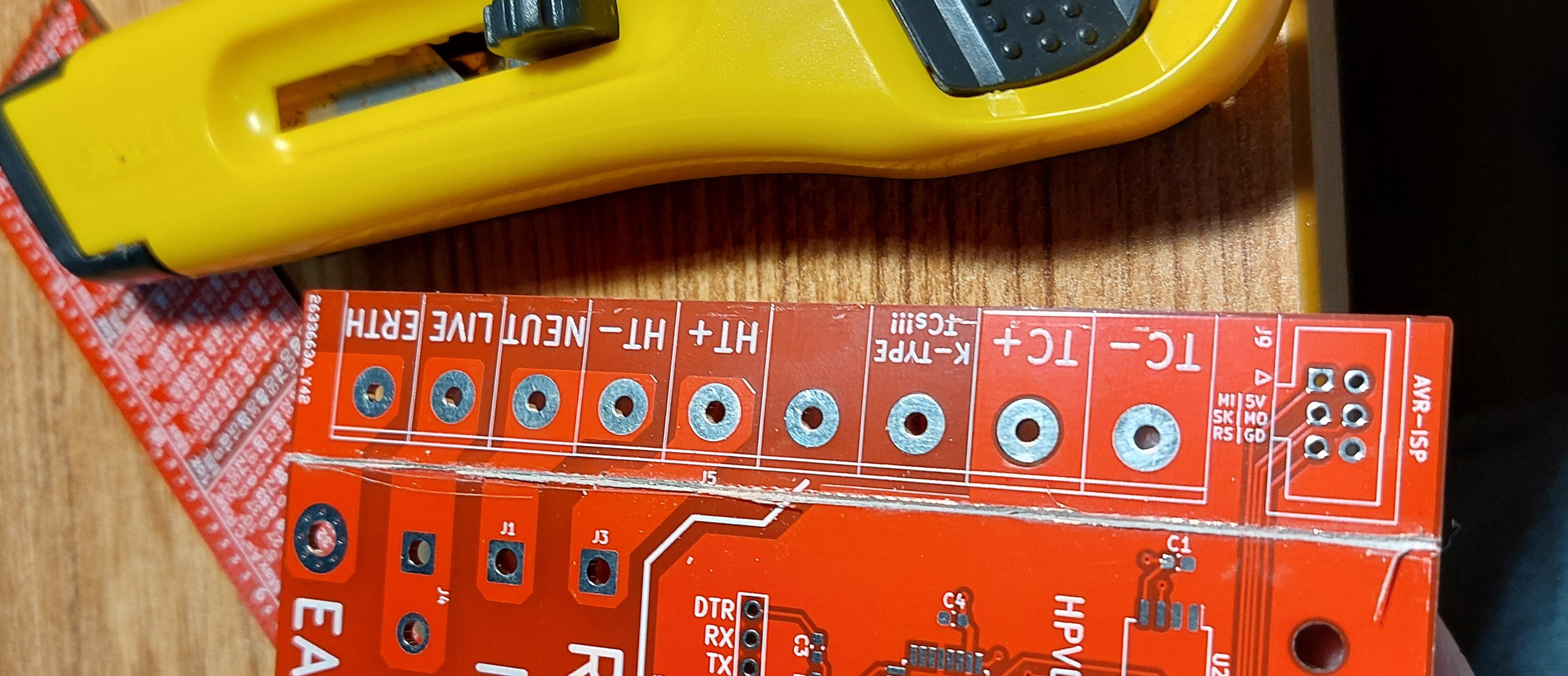
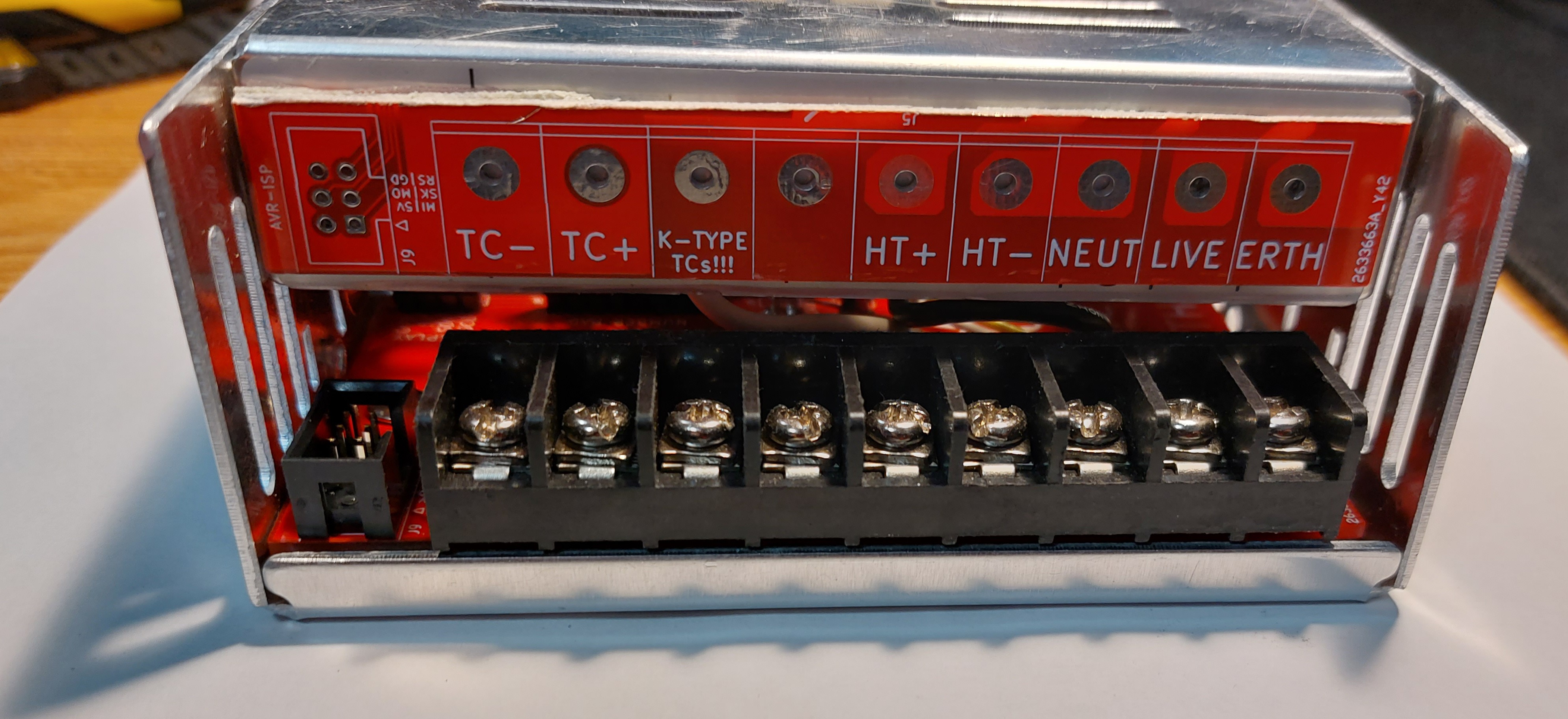
The final touch I added was using one of the spare boards and cutting it to use as a label for the screw terminals. (This is why I included labels for them even though I knew they would be covered when actually assembled). I used a knife and ruler to score a break line.
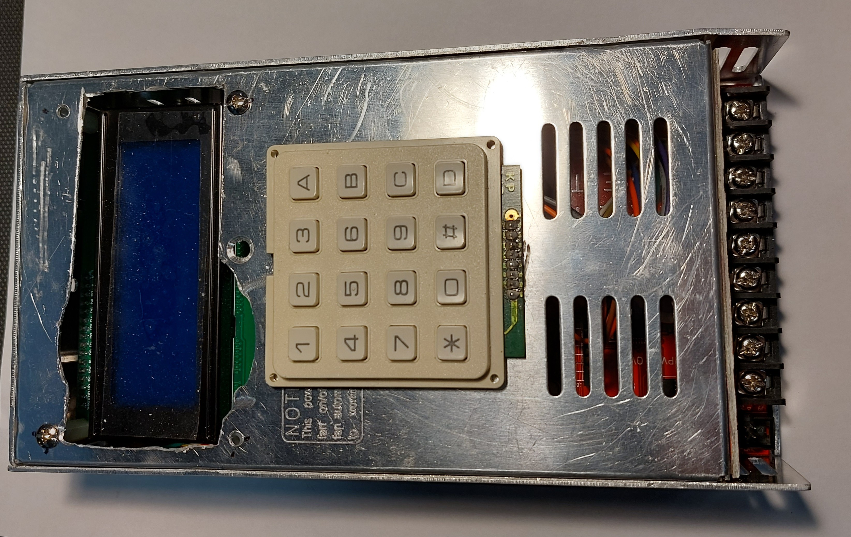
In the end, I had what is probably the project I have made that most resembles a movie bomb prop.
Testing and Coding
With the system assembled it began time to test the hardware and develop my code to the new hardware.
Power Test
The first test was honestly the most daunting, applying power and seeing if it holds as it should by design. This project in particular was scary thanks to the 120 V portion. Using a long power cable I placed it on the ground in my hallway and then I went back and around a corner to plug it in. After not hearing any notable explosions of the crackling of flames for a good 20 seconds or so after plugging it in I went and checked it out. The system was working fine, no shorts, and a steady 5 V supplied to the control electronics.
Programming
For programming I mainly intended to use AVR’s SPI in system programming, hence why I had exposed the header to do so, so it could be accessed when the system was fully assembled for easy reprogramming on the fly. With the power on and my programmer in place, I tried to burn the boot loader to the ATmega328P.
It failed. The chip was recognized but it failed to reply with the right device signature after some code was written to it. This was unexpected since I had used a chip I harvested off a working Arduino and I specifically tested SPI programming before transplanting it.
MAX6675 Issues
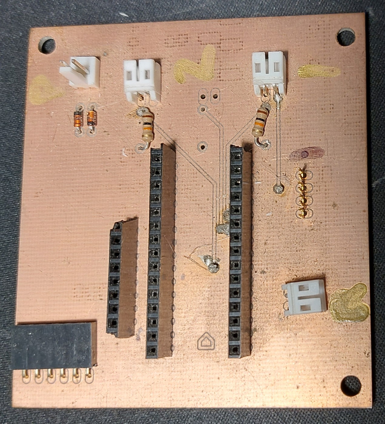
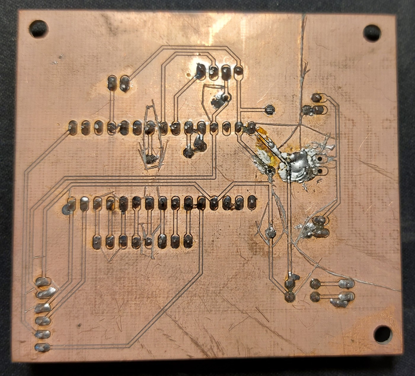
After some more failed attempts I thought that since the MAX6675 was sharing the same SPI bus it could be interfering in some way even if it wasn’t being selected. So I de-soldered it and took it off the board, and then tried programming the ATmega again. This time it worked without a hitch! Odd I thought, so I installed the spare MAX6675 I had in case the original one had been damaged. Before installing the new MAX chip I tested it to be sure it was functional.
With the new, functioning, MAX6675 chip in place, I tried programming over SPI. Once again it failed to program properly. I then took the chip off and tried again in its absence, worked again. I checked the connections and they were all the same as I had on my Arduino Nano that I was using for testing these MAX chips before installation so I was lost.
I returned the MAX chips to their module boards and tried them with my Arduinos to see if I had somehow damaged them both when transplanting them. They both worked correctly on their boards! What? I could even upload code over serial with them connected, although my code for these tests had the MAX chip connect to different (non-SPI) pins on the ATmegas.
I then tried to program the Arduino Nanos over SPI like I was doing with the oven board with the MAX modules attached, now exactly as they were in the oven (sharing the SPI pins). Sure enough, they also failed to be programmed correctly. I then moved the connections for the MAX back to the non-SPI pins I was using to test them. I tried programming over SPI again, and oddly enough it failed to program again!
THE MAX6675 WASN’T EVEN SHARING THE SIGNAL LINES! What?!
MAX6675 Workarounds
This really confused me, but it was clear that the only way to program this system was to have the MAX6675 removed when programming the ATmega over SPI. Once a boot loader for serial programming is programmed, the MAX6675 can be introduced, but not using any of the hardware SPI lines!
This could not be arranged with my current board, but it will be addressed in a future revision.
Display and Interface
I prepared some basic boiler plate code for the keypad to scan it and determine what button was pressed by multiplexing the rows and columns sequentially. It is not meant to handle more than one key press at a time, but is responsive otherwise. My code then returns the character pressed to the main code to handle as it pleases. This mainly is to enter numbers, and navigate my entry fields.
The display is dependant on a library to drive the 20 by 4 character LCD called NewLiquidCrystal_I2C. I basically go around the display and print text character by character. I prepared some basic functions to simplify the process of placing text aligned to either, the left, center, or right of a given row - and used them to print the menus for the user. The first two screens the user would navigate through would be to set the parameters for the bake and look roughly like this:
Target Temp.   [usr]
Rise Rt. c/m   [usr]
Hold time (m)  [usr]
<Prev   Stg #  Next>
After the user would input their settings (shown in the respective [usr] fields on each stage’s page), they would advance to the curing screen. This displays the time elapsed, end time, and heater state (on or off). Once the oven completes, it simply shows text to inform people that it is complete.
Temperature Reading
Originally the system used NTC (negative thermal coefficient) thermistors to monitor temperatures. A resistive voltage divider was set between these and set resistors of known values and the voltage monitored using the internal analog to digital converter in the ATmega. This would then be used to infer the temperature based on the characteristics of the NTC. This method proved to be very tedious to calibrate and even then inaccurate at high temperatures when the difference in resistance per degree change was approaching the what the ATmega’s ADC could quantify with its resolution.
With the MAX6675 it was super easy to read temperatures with no complicated math or processing required, just some bit shifting and then dividing by four. Thanks to a modular coding approach I was able to replace the previous NTC code easily with this after I ran some unit tests on it. Unfortunately I only tested using non-SPI pins for communication which led to the unforeseen issues with programming.
Currently the oven cannot read the temperature from the MAX6675 due to it being on the SPI line.
Curing Performance
Unfortunately due to the issues with reading temperature on the current board, I cannot use the system to cure some composites. It doesn’t help that the team broke our heater anyways so we need a new one.
Revision
To address the critical issue I have with the MAX6675 IC, I need a new board revision. Unless I decide to have a module floating about inside the enclosure. With it I will move the IC to use a completely separate bus from the real SPI pins. I will also add a buzzer to alert people to the oven’s status if they aren’t actively looking at the screen.

I hope to have this laid out and made by the end of April.