DATA Music Visualizer
Table of Contents
Overview
I wanted to make a little tribute to an album I really like, “DATA” by Tainy, to also serve as a pitch for a collaboration. Given the sci-fi theme of the album a custom circuit board was a perfect fit for it, and I realized that I could further elevate it by making it react to music through lights going around the edge. When the idea came to me I couldn’t help but go through with it!
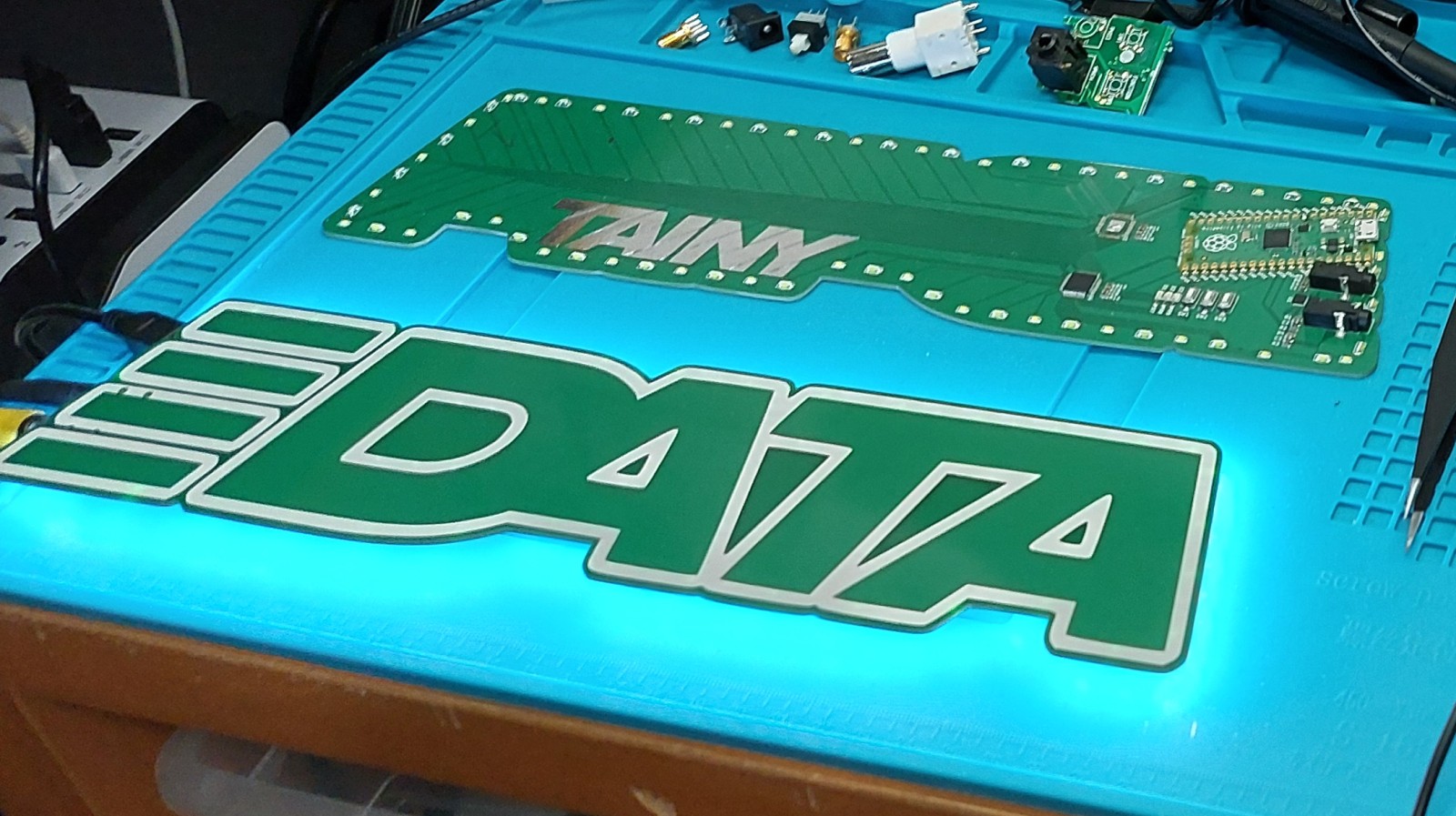
The final result was my physically largest board I’ve made to date which also has the most LEDs I’ve used yet (72)! The LEDs were both back and side facing so the illumination would be visible if the board was pressed against a wall or free-standing further away. The music was fed in via standard 3.5 mm aux plugs, where the board would pass the signal on to a normal amplifier/headphones/speakers. I also made the board interactive by using the tabs on the left side as sensing pads to allow for the effects to be changed or brightness adjusted.
I couldn’t have completed this as easily without the help of Elliott Muscat (really cool guy, check out his site!), the creative director for Tainy, who provided me the design of the logo in a format for me to use for the PCB when I asked.
Requirements
- Shine a bunch of LEDs in response to music passing through via aux
- Not distort the logo visually on the board
- Use the tabs to tune LED behaviour
- Impart minimal distortion on audio passing through
- Use only a single colour of LED (white)
Objectives
- Have over 10 different LED effects
- Have stereo audio effects
- Update the lights at a rate of 20 times a second or more
- Complete the project in under a month
Takeaways
The project was a success, one of my fastest turnarounds for an idea into reality taking only a couple of weeks to have it working at a basic level! I tuned the effects for a few weeks afterwards. It’s impressed most people I’ve had the chance to show it off to, and I enjoy seeing it run. I learned a fair bit about lighting planning and some basic audio interactions and I can confidently say that this was a completed project that achieved everything I wanted of it.
…That being said, there are always improvements to be made! Changing the PCB to white on black would definitely improve the look and be more faithful too. Even so I think this was a beautiful functional prototype, but if I were to really release it to the wild I would need to work a fair bit on improving its usability so people find it effortless to use. Some basic ideas would be to use a microphone instead of depending on an aux pass through since few people regularly use those, and even moving to a battery instead so it can be placed freely.
Detailed Report
As I was finishing my masters I got into Latin music, as I was searching for music with lyrics I couldn’t understand and thus distract me as I wrote my final report. This coincided with the release of Tainy’s album so it was being promoted and I was quickly hooked. Eventually through a chain of events ended up working next to the office of his creative director, Elliott, who I got to meet! We got along well talking about the album and our inspirations, thus I proposed that we could do a collaboration of sorts. As a preliminary pitch I showed him different boards including the ever famous raccoon as examples.
After chatting some more I decided to just go ahead and make a entire proposal to show him, and once the idea of combining the circuit board with lights and sound came to me, I decided to jump right in.
Schematic Design
In the interest of keeping this project moving fast, I didn’t want to take many risks with the circuit design lest they fail and I lose a lot of time either bodging it to work or ordering a new revision. As a result the design of the board is pretty simple electrically, a few chips and parts that are connected directly to a soldered on microcontroller development board.
For the DATA board I selected the Raspberry Pi Pico for the RP2040 as the microcontroller board because it was designed to be soldered as a surface mount module which would spare the art on the top side of the PCB. It also is a capable and fast microcontroller which would be needed for the audio processing I foresaw, with its dual core it even opened the opportunity to split tasks to be completed in parallel such as collecting audio data and then processing it.
User Interaction
Indispensable on any prototype circuit board is at least one light and button for the microcontroller to interact with directly, so I had three of each on the board. This way I would have a reliable way to get some feedback in or out of the system if the other supporting chips were not working as intended.
As I mentioned earlier I wanted the users to be able to operate the system using the tabs on the left of the logo as buttons. This would be done using capacitive sensing, which warrants another shameless throwback to the raccoon where I used it before. Unlike the hack I used in the first version of the raccoon, I would use a dedicated capacitive sensing chip for this: a CAP1206. This would make the operation more reliable, especially with multiple channels. It has six channels so in addition to the four tabs I also intended to connect the “DA” and “TA” as additional possible buttons.
Bright, Bright LEDs
White LEDs ONLY! For the sake of circuit simplicity and style I elected to only use white LEDs to match the eventual black PCB. Going with a single colour of light meant that I didn’t have to concern myself with a minimum distance to ensure proper diffusion (mixing of separate lights) when they would be close to a surface. I personally find poorly diffused lights annoying and cheap looking so I generally try to avoid RGB LEDs for this reason. Also I find that by committing to a single colour you give yourself some constraints to work with creatively rather than having the whole gamut of colour at your command.
I wanted there to be several dozen LEDs around the edge so that the lighting effects could be granular, with each LED having its brightness individually controlled. To attempt this using the conventional resistor and LED connected to a microcontroller pin is futile for several reasons:
- The RP2040 only has around 35 pins total, and several are already being used for other things
- It is unlikely we would be able to use PWM to dim each LED individually
- The RP2040 wouldn’t be able to supply all the current needed if all LEDs needed to be on at once
- I would need a resistor for each individual LED and their variation in resistance would cause nonidentical current and thus brightness at the same duty
For these reasons I used two discrete LED driver chips, the IS31FL3236A. These are puppetted digitally from the RP2040 to allow each of their 36 LEDs to be controlled independently and also only need a single reference resistor to set the current across all LEDs for a given chip reducing brightness variation. They had the added benefit of an advertized PWM frequency of 22 kHz which meant that with the right configuration there would be no audible noise introduced to the system which might contaminate the audio signal passing through.
Audio Input
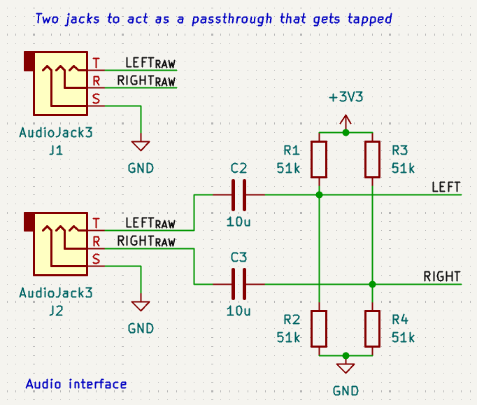
I had to look around online on how to best handle audio inputs for microcontrollers. The obvious “best” performance came from using a dedicated audio-grade analog to digital converter, however I did not have the fiscal nor temporal budget to allow myself such luxury so I opted for a cheaper and dirtier approach: using the microcontroller’s own onboard convertor connected to the audio lines using a capacitor and biasing resistors. The audio would pass directly from one aux jack to the next, with each stereo channel being “T”’d off for sampling via the circuit described.
Printed Circuit Board Design
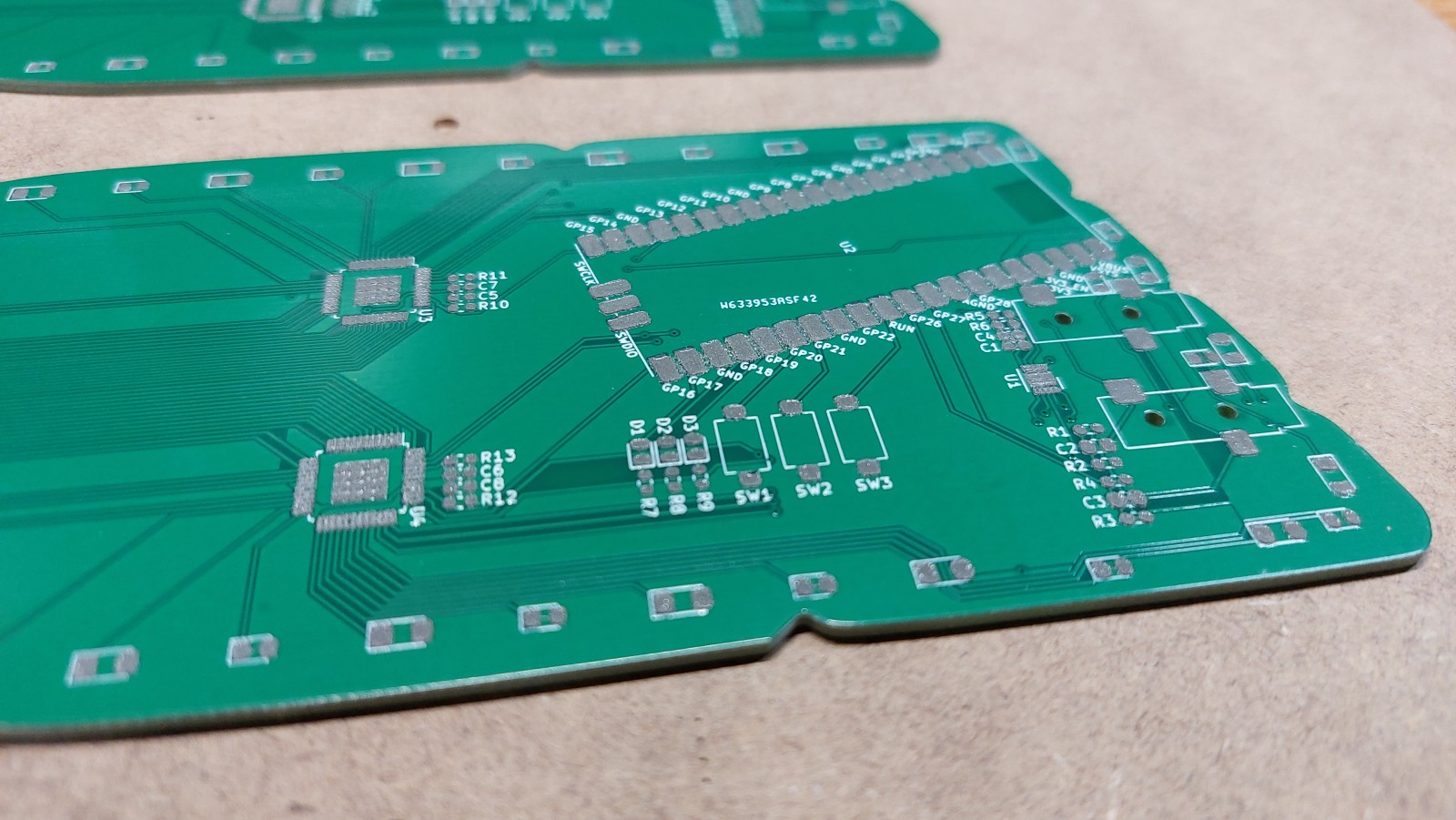
The layout of this circuit board carried some characteristic constraints for artistic boards, namely not messing with the art where possible. To that end, I put all parts on the back of the PCB, and made an effort to route the majority of connections on the back too.
To start the design of the PCB I needed the logo, so I reached out to Elliot and asked him for a version in gray scale so it would be easier for me to process into the different layers I needed for the board (copper, outline, silkscreen, etc.), which he generously provided - the one I showed at the start but I’ll repeat here. The file name implied it was meant for hoodies.
I wanted this to be a visible board, an art piece of sorts, so I needed to make sure it was appropriately sized. I wanted the height to be 70 mm (about 2.75") since I felt any shorter would’ve made the tabs along the side small to operate since they would only be about 13 mm (about 0.5"), and the entire board likely feel tiny. The wide aspect ratio of the logo meant that to have that height, the board was going to be almost 300 mm (12") wide!
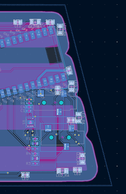
In my view it made the most sense to have all the cables come in on one of the sides, so I decided the left side where the tabs are, as this would be where the user’s focus would naturally be directed to interact with the board. This strongly influenced me to put all the computation and control circuitry in the same area to simplify routing the signals.
The LEDs followed the perimeter of the board, alternating between up- or side-facing LEDs to ensure an approximately even illumination around the board regardless the distance to a wall from behind. There were some tough to place lights around the computation area due to the components and connectors present - although their disruption was minimized as best I could.
Circuit Art Technique Demonstration
As part of my proposal I intended to show the different ways one could do art with a PCB so I did a couple little patches to demonstrate different techniques so we could refer to them in future discussions:
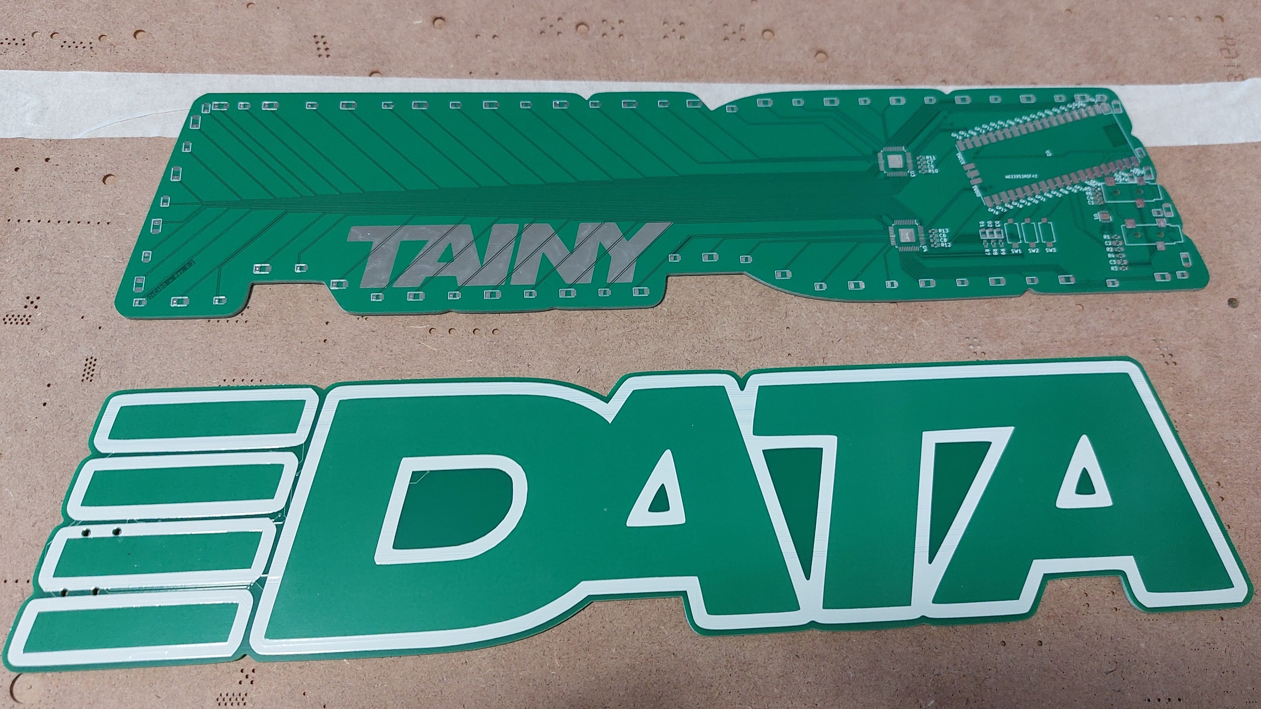
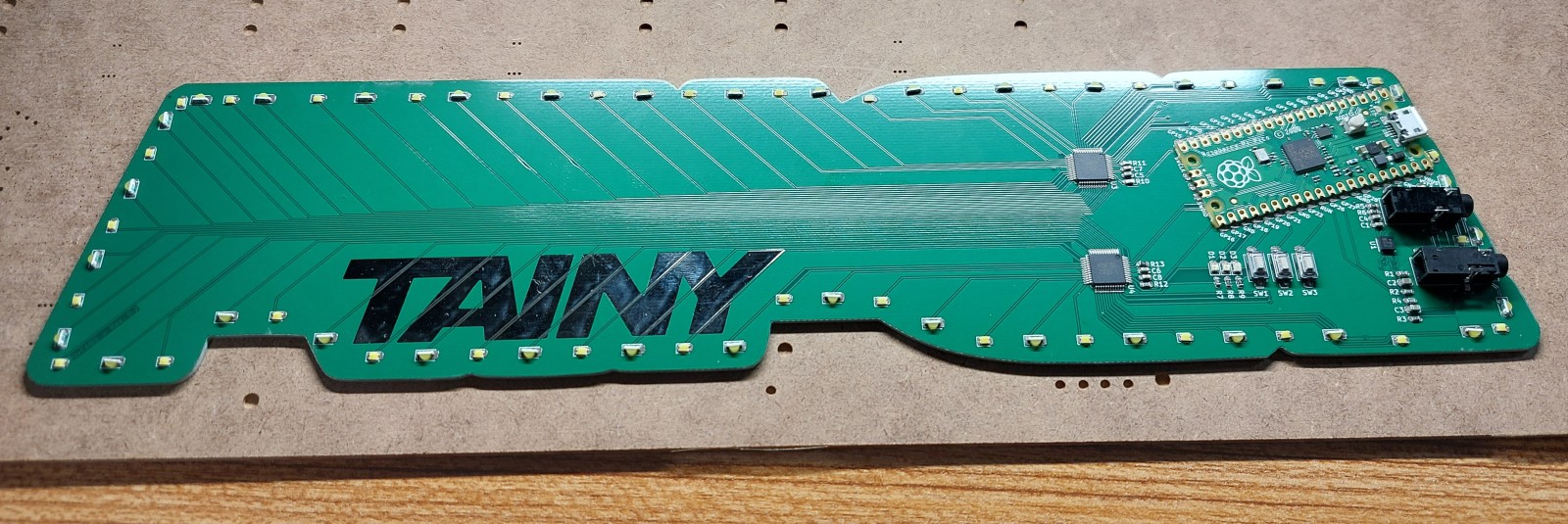
- The front was done in a very simple style with no exposed copper, thus it depended heavily on the white silkscreen for details and contrast.
- On the rear I cut out “TAINY” from the solder mask (green coating) which revealed the traces beneath which became shiny, almost reflective. This could be made golden like I did for features on the raccoons.
- I did organic “spaghetti” routing near the computation region of the board where all the chips are
- For the LED signals I routed the traces in a more conventional parallel bus that fanned out to LEDs
- I did want to have the traces to the LEDs go from a rigid typical straight lines at the chips to eventually more organic and curvy forms near the LEDs mirroring the gradual humanization of the album. Unfortunately I was unfamiliar with how to achieve it at the time and I wanted something done quick so I skipped that.
Honestly laying out the board wasn’t too tough, even trying to keep things to a single layer was easy as there weren’t that many connections that needed to cross one another. Whenever I could I would reassign pins to prevent the need to cross signal paths. The only real challenging part that I would like to change in the future is moving away from a RPi Pico board to a proper embedded microcontroller since its large footprint was annoying.
Assembly
Not much to report here. I opted for a manual assembly to reduce personal cost but also expedite their completion by a few days. It was a pretty simple assembly process, only catch was the hulking size of the boards which meant I really had to be careful not to rest my hands on the board by accident before fixing the parts into place via reflow soldering.
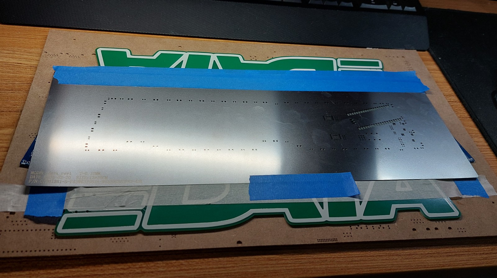
The process was the standard for surface mount parts: stencil alignment, paste application, part placement, reflow.
I started the project on the 14th of February or so, and these photos imply that I finished the assembly on 26th, so sub-two week turnaround!
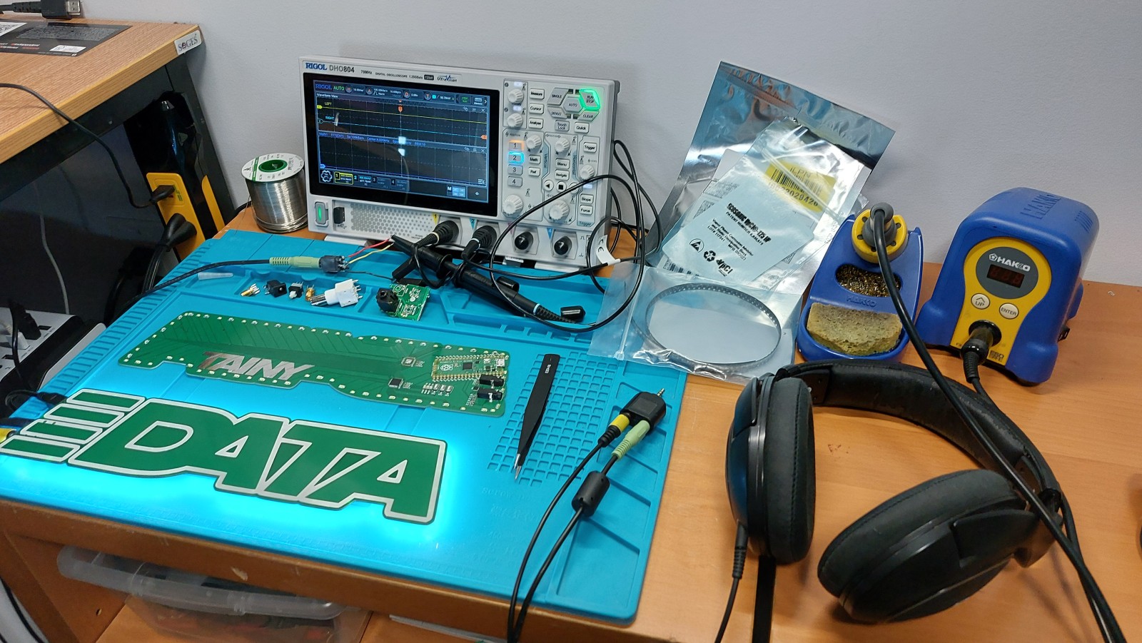
Initial Testing
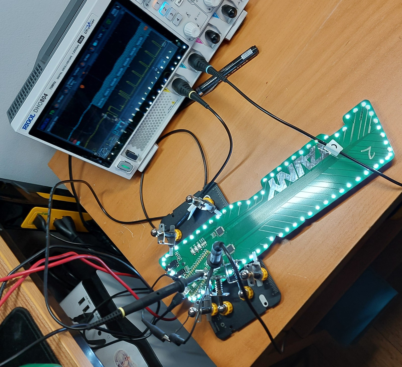
Initial hardware testing wasn’t too difficult a time. The only hard part was getting the right aux cables to test with as I had accidentally tucked the connectors slightly too far from the edge so I needed to whittle some of the encasing of the aux cables off. Luckily I had properly placed the RPi Pico well so that USB cables had no issue plugging into it.
Once I had the system connected and powered for the first time I observed no smoke or otherwise spectacularly failing components, and the power supply was verified to be at the expected level - so I had nothing left to do but move to programming and testing each bit of code.
Programming
For programming I took a back-to-front approach; I programmed the output stage (LEDs) first, so that then I would be able to reliably observe my work on the stages feeding into it, and thus the stages feeding into those. Once I had built up a verified pipeline from audio to LED, I would expand on the lighting effects offered.
Since I was looking for a fast time to completion I selected the Arduino framework for this project as I was familiar with it and it would likely have some libraries that would spare me some of the work.
LED Code
Getting the LEDs working wasn’t too hard, the driver chips were pretty straight forward to interact with. The only thing that really tripped me up with them was that their I2C addressing was a little confusing, which was compounded by the fact that they only acknowledged write commands; thus they didn’t appear when I ran a normal I2C address scanning program which checked for device by requesting data from them. Once I got talking to the right address I had the lights going in no time!
Anyone can make an LED turn on, it takes some skill to make something ✨ sparkle ✨. So to properly control the LEDs I had to implement two things that were critical for this project. Firstly I had to set the chip into that ultrasonic 22 kHz switching mode so the LEDs wouldn’t potentially emit an audible hum as the default frequency is 3 kHz which is well within audible range. The second notable thing is a key part of any light art project like this, gamma level correction.
Gamma correction is the process of dealing with humans not perceiving light intensity in a linear fashion. I’ll leave the full explanation to the Wikipedia page, but in short it can be approximated as a exponential fit instead - so going from 10% to 20% brightness is a smaller jump in LED power than to go from 80% to 90% brightness. Therefore I needed to do some math to convert between the desired perceived intensity and the appropriate LED power levels. To make my code run faster I limited it to 64 perceived brightness levels and recorded the corresponding calculated LED levels in a look up table (LUT) for the code to use rather than running the calculations every time.
Audio Code
Once I had the system powered and connected, I began testing the audio input. Fortunately it worked without major issue. However it did have some difficulty at first and imparted some buzzing to the audio when I was using my desktop as the audio source although it didn’t seem to affect the RPi’s audio readings. When I switched to my phone it went away. I attribute this to likely be the cause of the longer run of cables from my computer’s audio output compared to the phone’s.
Reading the audio level is fine for some basic effects where one is only concerned with the volume of the music which can be inferred from the amplitude of the signal, and this is what I started with. However to get a better representation of the audio you should use small snippets of multiple samples as this will give you a better idea of the audio in the event you have a sample at the hit of a drum or in the break which would misrepresent the average volume. These snippets also allow for the calculation of a “spectrum” analysis where you can see the presence of different frequencies in the audio which can them be used for more advanced spectrographic effects - think old 2000’s audio player visualizations! Granted this microcontroller doesn’t have the same computational power for those.

The actual math used to get the spectrograph for a string of samples I used is called the Fast Fourier Transform (FFT), a common technique for this sort of thing where speed is prized at some cost in accuracy. There are many libraries out there for this, I opted for this arduinoFFT from kosme. The setup I used is copied below, note that I did have it perform separate processing for the left and right audio channels.
const uint16_t NUM_AUDIO_SAMPLES = 128; // Number of samples taken for audio FFT
const uint16_t NUM_SPECTRUM = NUM_AUDIO_SAMPLES / 2; // Number of entries in the audio spectrograph

const double SAMPLE_FREQ = 25641; // Results in almost 200 Hz wide buckets
const unsigned int SAMPLE_PER_US = 1000000.0 * (1.0 / SAMPLE_FREQ);

double vReal_R[NUM_AUDIO_SAMPLES];
double vImag_R[NUM_AUDIO_SAMPLES];
double vReal_L[NUM_AUDIO_SAMPLES];
double vImag_L[NUM_AUDIO_SAMPLES];
int16_t wave_R[NUM_AUDIO_SAMPLES];
int16_t wave_L[NUM_AUDIO_SAMPLES];

arduinoFFT FFTright = arduinoFFT(vReal_R, vImag_R, NUM_AUDIO_SAMPLES, SAMPLE_FREQ);
arduinoFFT FFTleft = arduinoFFT(vReal_L, vImag_L, NUM_AUDIO_SAMPLES, SAMPLE_FREQ);
The actual computation code is pretty simple thanks to that library.
// FFT Calculation (33ms)
FFTright.Windowing(FFT_WIN_TYP_HAMMING, FFT_FORWARD);
FFTleft.Windowing(FFT_WIN_TYP_HAMMING, FFT_FORWARD);

FFTright.Compute(FFT_FORWARD);
FFTleft.Compute(FFT_FORWARD);

FFTright.ComplexToMagnitude();
FFTleft.ComplexToMagnitude();
// Magnitude is in `vReal_x` arrays
Much like light brightness, sound is perceived in an exponential scale, so I performed some linearization. Unlike the LEDs, I did not opt for the lookup table approach as there are far too many possible values for loudness so I actually had the system compute these manually every time. Luckily these calculations were far less numerous than the ones would be for the LEDs. I used the following code for this, which also was meant to bring the loudness to a value between 0 and 1.0 so it could be scaled in later effect stages.
#include <math.h>

double normalizeFreqMag(double mag) {
    const double OFFSET = 1.5;
    const double SCALING = 1.0 / OFFSET;

    double fy;
    fy = SCALING * (log10(mag) + OFFSET);

    if (fy < 0) fy = 0;
    else if (fy > 1.0) fy = 1.0;

    return fy;
}
User Interaction Code
To get the system going I made use of the buttons and LEDs directly wired to the RP2040 for me to control, nothing too crazy there - just some digitalRead() and digitalWrite() calls. The real meat of this is the capacitance sensor chip, which was my first time using one, or really any “proper” capacitance sensing system.
The CAP1206 did a good job of doing away with a lot of the work on my behalf. Once configured I would just poll it to see which pads were pressed and pass that on, and periodically the code would trigger a re-calibration of the CAP1206 which it would perform internally to accommodate any potential changes in environment. Granted that initial configuration was long compared to most other chips I’ve used (about 15 functions for different groups of settings), but I guess that’s the price of offloading so much work that then your main code is far simpler.
Overall I think that I would reuse the CAP1206 in a heartbeat if I found myself in a project needing capacitive sensing as it had lots of useful features I disabled or ignored altogether for this board.
Once I had the chip working I did some tests and found that it would work dependably on the four main tabs I intended to use - unfortunately for me though the large pads for “DA” and “TA” didn’t work and after some tinkering I gave up on them to focus on the four tabs and developing the rest of the system.
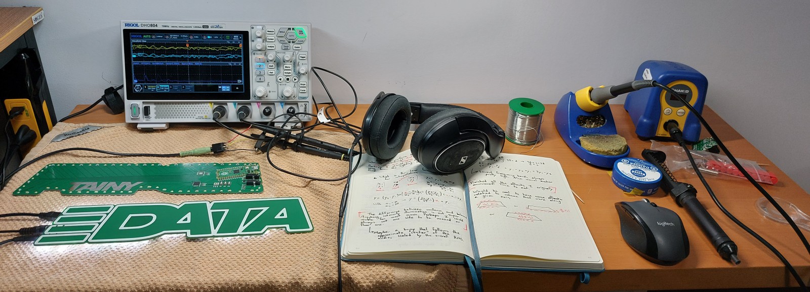
Effects Code
With the foundation of the system complete, I had the freedom to build whatever effects I wanted, so I drafted a few in my notebook and then got to working on them. Unfortunately I don’t have my notebook handy as I write this currently so I’ll likely flesh this out more in the future.
My first “effect” was simply a constant and uniform brightness on the LEDs which could be adjusted using the tabs to ensure that the LEDs and tabs were working as intended. After that I made the lights respond in a uniform brightness based on the volume of the audio coming in to ensure the basic audio was working too.
Since I wanted a multitude of effects I had to plan ahead to prevent my code becoming a mess. For simplicity and extensibility I decided each effect would be a “state” and coded as a separate function, where two buttons would change the state and the other two would control a “user scalar” that could be used by effects to adjust them, for example to control the brightness mentioned before.
if (override) state = overrideState;
switch (state) {
case ledFSMstates::BREATH:
    breathingLED(5000);
    if (returnState) state = ledFSMstates::SOLID;
    if (advanceState) state = ledFSMstates::SPINNING;
    break;
case ledFSMstates::SPINNING:
    spinningLED(5000, userControl);
    if (returnState) state = ledFSMstates::BREATH;
    if (advanceState) state = ledFSMstates::SWEEP;
    break;
case ledFSMstates::SWEEP:
    sweepLED(500, 500, toggleUser);
    if (returnState) state = ledFSMstates::SPINNING;
    if (advanceState) state = ledFSMstates::SWAY;
    break;
...
These states would control not only the illumination but also what kind of audio processing would be done. Although we could maintain the 20 updates per second in the most intense processing (dual spectrographs), if it wasn’t needed we could go to a simpler but sufficient method to achieve faster updates.
// Decide what audio processing is needed for the next cycle
// Uses a lot of "fall-through cases" to collect multiple states
switch (state) {
case ledFSMstates::AUD_HORI_SPECTRUM:
case ledFSMstates::AUD_SPLIT:
case ledFSMstates::AUD_SPLIT_SPIN:
    sampleAudio = AudioProcessing::SPECTRUM;
    break;
case ledFSMstates::AUD_UNI:
case ledFSMstates::AUD_BALANCE:
case ledFSMstates::AUD_VERT_VOL:
case ledFSMstates::AUD_HORI_VOL:
case ledFSMstates::AUD_HORI_SPLIT_VOL:
    sampleAudio = AudioProcessing::RMS_ONLY;
    break;
default:
    sampleAudio = AudioProcessing::NO_AUDIO;
    break;
}
Once I had the frame work set up it was pretty easy and fun to add in additional lighting effects and schemes. The only thing that would occasionally catch me is failing to update the transitions for the existing effects to include the new effect. In the end I prepared almost 20 different effects for the board, about half of which were responsive to audio.
In retrospect this did start to feel a bit unwieldy as I got past a dozen “states” but I kept the framework in place, I wonder how I could make this better going forward. Then again, it worked just fine which I guess is the important thing here.
Reflections
This was a success in my book, a tightly defined project delivered in record time, that was fun to do and show off. Sadly life got in the way and I haven’t yet been able to show Elliott the final product in person - maybe some day in future. I’ve enjoyed having the board and displaying it nonetheless.
In terms of lessons I learned, the main one that stuck out to me at the time was the audio processing and playing with FFTs; the capacitance sensor although novel was really “just” another sensor I wrote a driver for at the end of the day.
As the dust settled I noticed many of minor shortsighted things I would like to change in terms of the hardware design which shouldn’t surprize anyone who’s made something in a week: many compromises were made from a usability standpoint in the interest of completion speed and minimizing the chances something failed and would hold back the project. That’s the real lesson I feel now looking back on this; knowing the true drawbacks of usability compromises and when to take them - after all what good is technology that no one finds convenient to use?
Future Improvements
As it stands I’m not sure about a return to this project soon, life’s gotten quite busy for me and I don’t have much time to spare. Should I or anyone else decide to pick up the project again I would advise them to consider the following changes, namely for portability.
- Switch from aux to a microphone. Using an aux pass through isn’t super convenient for many people and force the board to live in proximity to audio device rather than on display. Using a microphone to listen for audio would allow for freer placement of the board, aux can still remain as a possible input.
- Make it battery powered. For much the same reason as the microphone, it would be handy to move it around freely. The cell if placed cleverly on the back could act as a supporting leg for the board to stand upright on a table without a separate stand part.
- Shrink the board so it is easier to place.
- Either ditch or tune stereo effects. They currently require double the processing of mono effects but fail to be visually distinct from the mono effects, maybe they just need to be adjusted to be more evident.
- Add a system to detect proximity to a wall and adjust the lighting of LEDs to suit based on their orientation.