Flight Controller V2
Table of Contents
Overview
This was my second design of a flight controller/computer, designed to be more capable than the first by using a higher-end microcontroller. This should enable it to run more complicated code before hitting limits such as memory or runtime that would cause it to fail to control the drone effectively.
The microcontroller I selected to use instead of the ATmega328P in the previous one is the STM32F103CBT which has far more features than the ATmega but is still decently cheap and approachable for tinkers like myself, with a lot of community support in open-source forums and projects like Arduino.
Circuit design was not too difficult, although I did have some issues with trying to layout the traces on the board to minimize the number of vias I needed.
I have done some development on it but have not worked on it much so I could focus on my classwork and finishing the ESC. I look forward to getting back into it though.
Requirements
In addition to the general ones outlined for all flight controllers:
- Use the STM32F103CBT microcontroller as the heart of the system
Takeaways
- Using an actual ST-Link compared to programming over Serial is much faster
- Using PlatformIO over Arduino enables me to code more efficiently and allows me to do certain things I couldn’t before.
Detailed Report
This was in a sense my real flight controller project, the previous was meant just as a back up if this one flops entirely.
By using an STM32F103 it has far more computational power, from a raw clock rate of 70 MHz compared to 16 MHz, as well as being 32-bit instead of 8-bit. Furthermore it has more features such as additional communication hardware and more timers and counters one can use which might prove helpful when working on control programming or future additions to the drone. One nice feature I have been making use of is native USB support so I can connect it directly with my computer for debugging.
Other than accommodating the change in microcontroller, very little has changed from V1 to this in terms of design.
Likewise, the assembly of the boards was also a success and easier than with other boards I’ve made for the drone since all components are on one side. I made two boards so I would have a backup.
Development has proceeded a bit with me setting up a framework to work in PlatformIO and testing out some basic programs. I find myself using the ST-Link I have for programming and then the USB connection for printing debug messages. I have tried, but not succeeded in setting it up so that I can use the USB connection for both programming and debug messages.
With the framework prepared I have gone on to start implementing some basic functions and preparing a library for interacting with the barometer.
Circuit Design
Although an easy change to say “I just changed the microcontroler”, I actually entailed a fair bit of revision to the circuit. It started with the obvious replacement of the ATmega and the circuitry needed for it operate, with the STM32 and its needed peripheral components. This led to some knock-on changes:
- Since all ICs on the board operated at 3.3 V, there was no need for 5 V and thus the 5 V regulator was removed
- 5 V is needed from an external source to the board though, it does not use the battery as a supply for the 3.3 V regulator
- Had to reroute the 3.3 V I2C bus to connect to the STM32 instead of the 5 V one
- A Mini-USB connection was added
- Three status LEDs were added to the design
- There are fewer exp[licit extra inputs/outputs broken out (as opposed to re-purposing the Serial header for example)

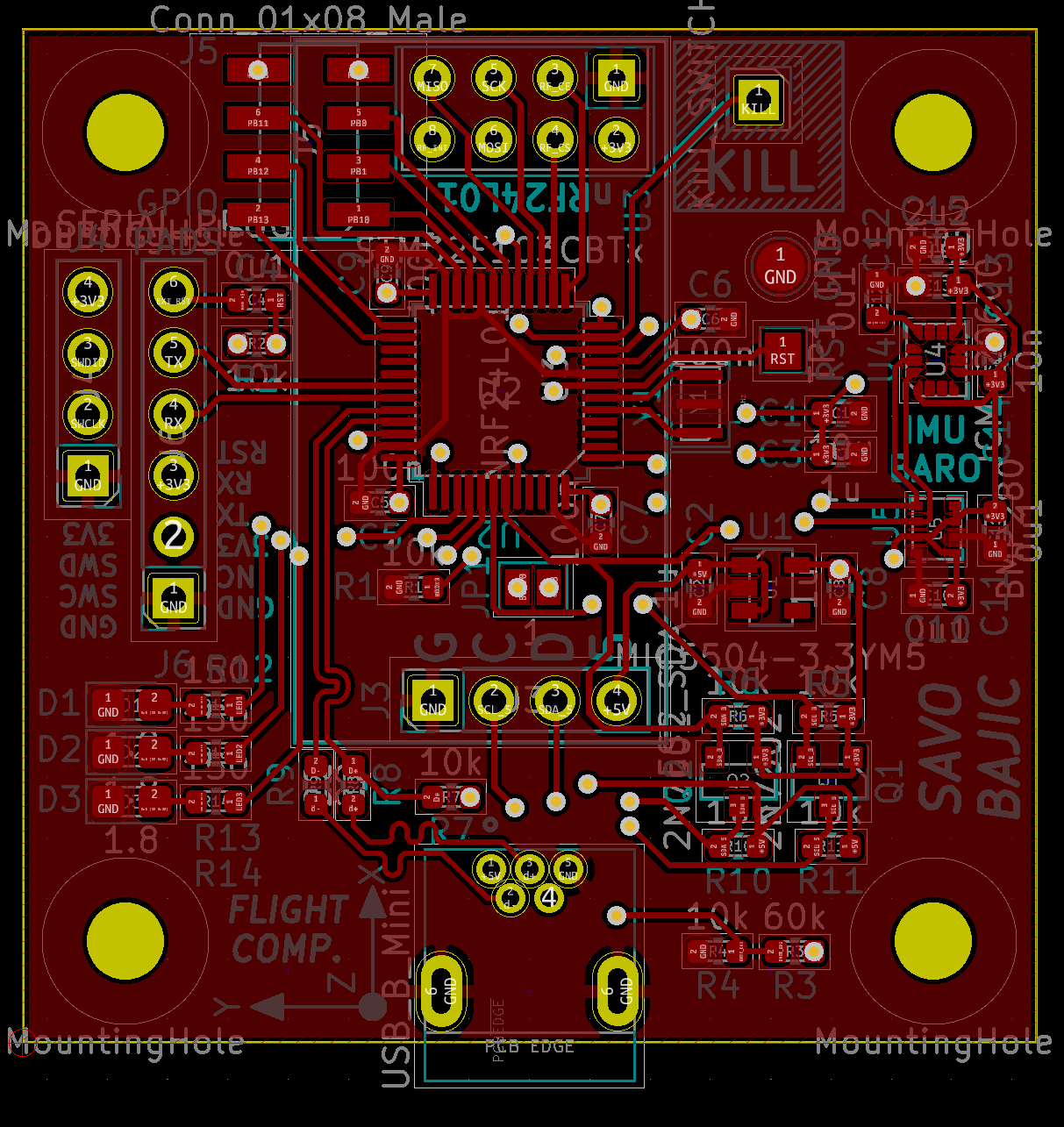
Layout
As a result of the circuit changes the entire board had to basically be rerouted from scratch. This time the board 42 by 42 mm, but still only two layered.
This increased area helped me put all components on the top side, as well as most of the traces, leaving the bottom to be used primarily for the power distribution and a few traces that needed to cross others on the top. This will make assembly easier because I will only need to put paste and parts on one side instead of two.
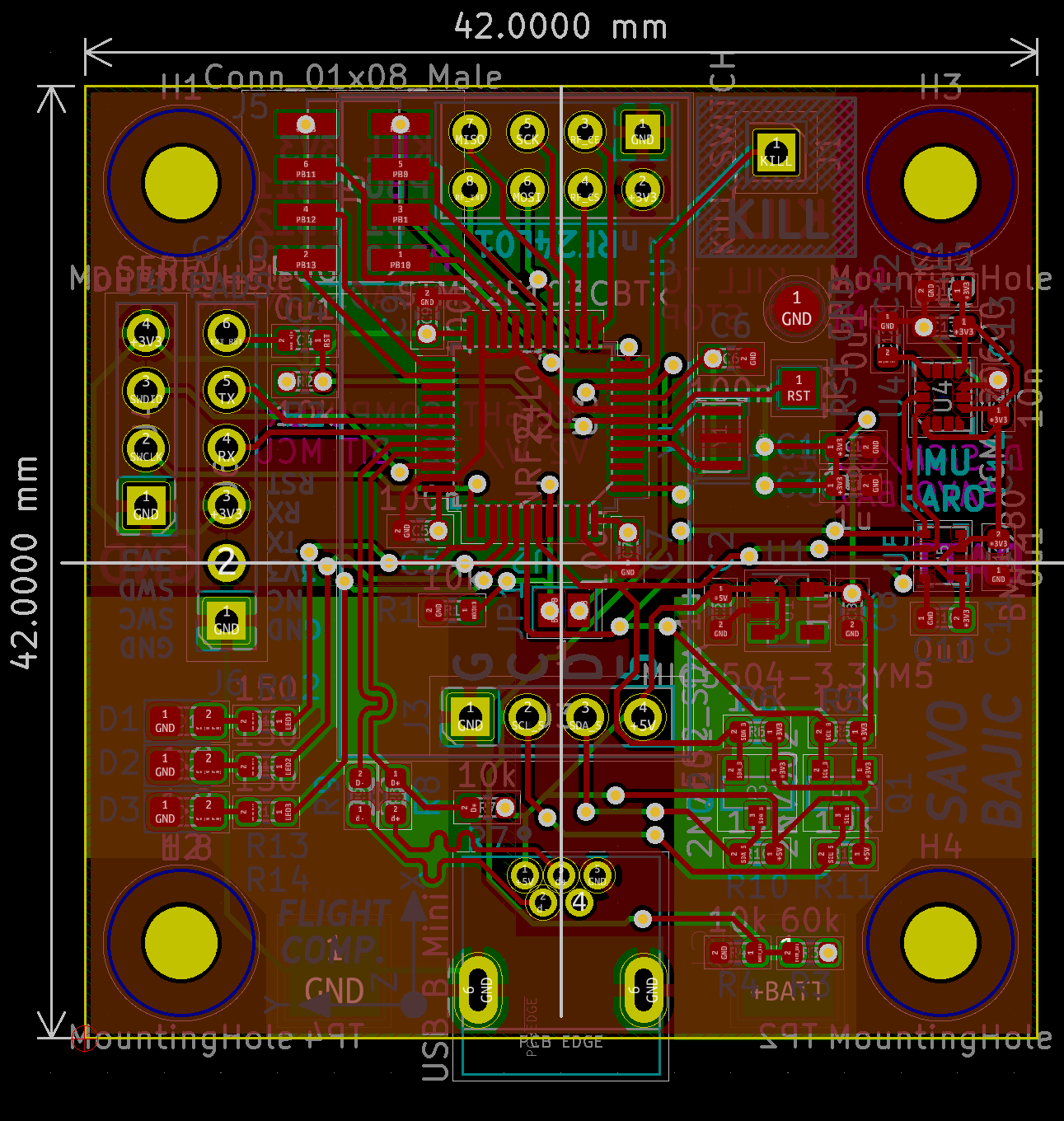
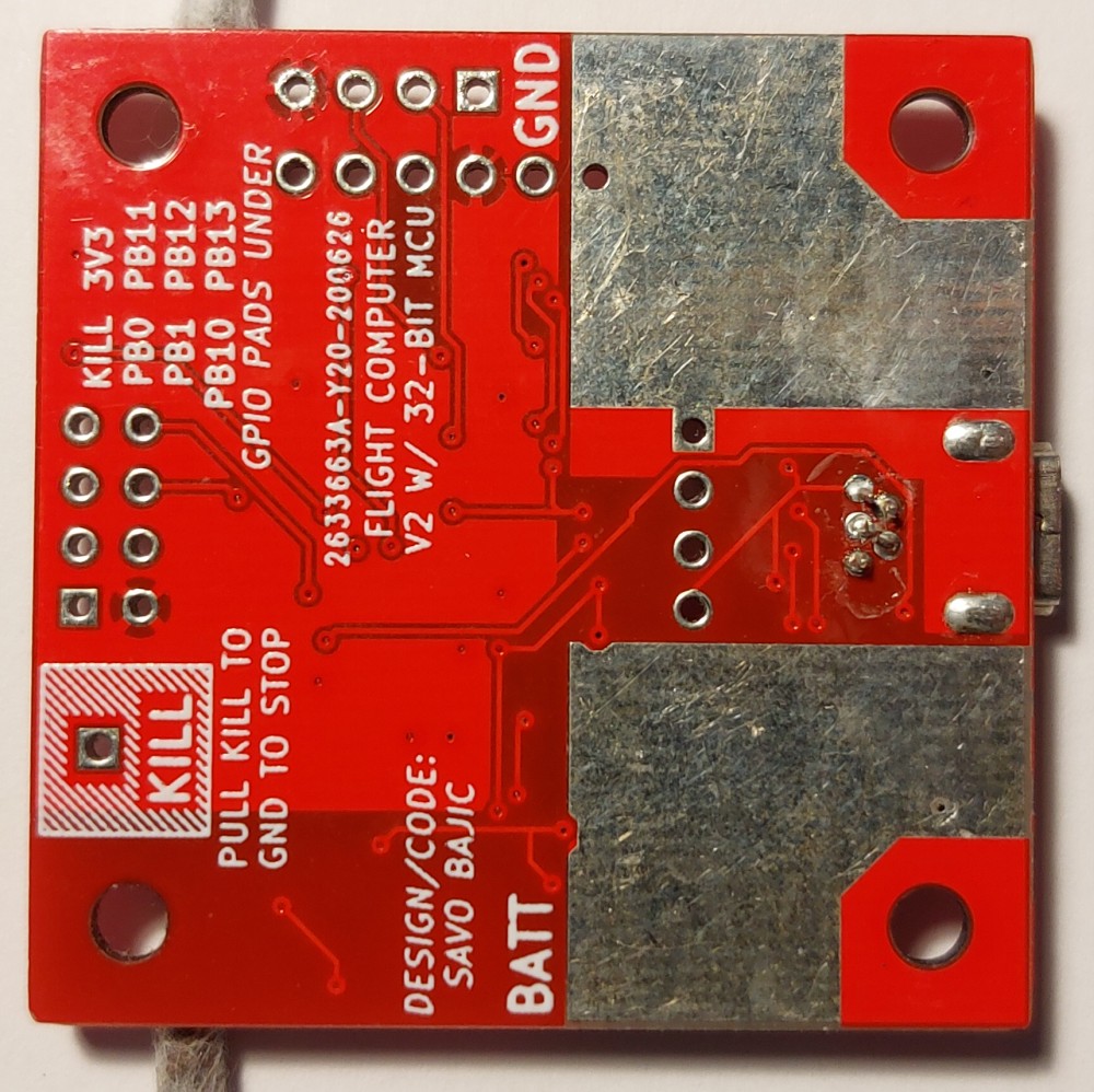
The top houses all the components of the board. Like with V1, I centred the microcontroller and had it fan out to the other parts of the circuit. On the left are the programming headers and status LEDs, the bottom is for the USB connection and I2C level shifters, the right houses the onboard sensors, the top for the nRF24 connector and the general purpose input/outputs.
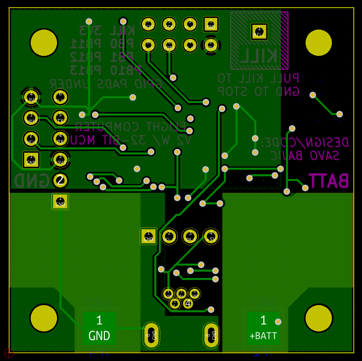
The bottom is used mainly for power distribution on the lower half, with just som miscellaneous traces on the top half and some informational text. I specify that the KILL signal needs to be pulled to ground to trigger this is because that can be easily scaled up as I add parts to the system rather than making a daisy-chained signal to break.
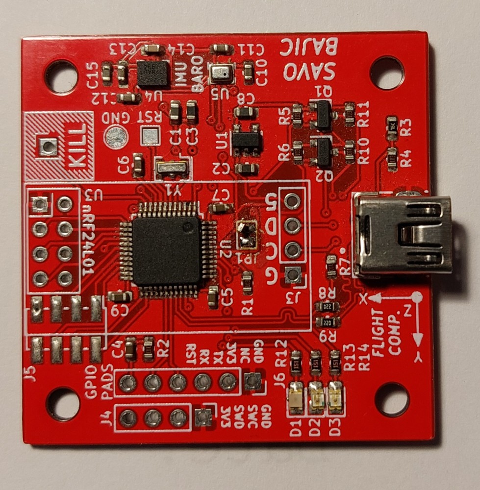
Assembly
Assembly of the boards was pretty simple. Having all the components on one side made it an easier board to assemble than if I had put component on both side like I did for my other drone boards, even if the board was a bit more crowded on that side.
Testing
I started with the usual, checking for any shorts between adjacent pins and power lines with a multimeter, then I applied power and verified that the regulator was working as expected, producing a steady 3.3 V. I then left the system powered for a few minutes to monitor current draw and ensure none of the ICs were getting warm. None did.
After the basic power tests were done, I started testing the STM32 by programming it. This was initially done with over the Serial programming connection with the Arduino IDE. The first few programs worked fine, such as the I2C bus scanner to verify that the sensors were responding correctly. Afterwards I burned the bootloader that would allow the STM32 to be programmed over USB in “Device Firmware Upgrade” (DFU) mode. I then verified that this worked as expected.
All testing to this moment has been done with exclusively the onboard components, I have yet to connect any ESCs or the nRF24 module to it. This will continue until I am satisfied with the board’s ability to monitor its state properly with the sensors.
During my work on trying to interface the sensors I grew frustrated with the limitations of the Arduino IDE so I decided to migrate to using PlatformIO within VS Code. This brought me many improvements in keeping my code easy to edit and work with. However I quickly learned that for some reason, PlatformIO could upload code using USB DFU, however it would erase the bootloader for DFU mode in the process. This needed me to re-burn the bootloader every time I wanted to upload code, so I decided to go ahead and jump (painlessly so) to using the ST-Link for programming. This worked on my first try and was faster in addition to enabling me to use debugging features on the microcontroller to step through code, monitor variables, etc.
Developing Firmware
I started writing code in the Arduino IDE due to familiarity with the platform. Once I realized the scope of my project I considered using the STM32CudeIDE offered by ST, however it was a bit too professional for me so I went back and found PlatformIO which runs out of VS Code. This would allow me to use the Arduino framework while having access to more professional features, such as code completion and debugging on-chip. The main improvement was simply the ease at which I could navigate and organize my code compared to the Arduino IDE.
My overall plan for the firmware is roughly:
- Get a working flow to upload code
- Collect sensor data reliably
- Develop algorithm on STM32 to monitor drone state
- Implement wireless communication
- Start developing control and stabilization algorithms, with ESCs and motors connected
USB Fun
The first step was to establish my programming flow. Originally I wanted to have it programmed over USB in DFU mode like I was used to with the Arduino IDE. However this was for reasons beyond me not feasible with PlatformIO (at least back in 2020) so I switched to using the ST-Link to upload code, and only using USB to exchange data with the computer. By using the ST-Link I unlocked the ability to do on chip debugging.
Although I was unable to program over USB, I found that I can set the STM32’s appearance when plugged into a computer so I had some fun with that, setting the vendor and device IDs and strings to my own desired values. CAB0 is an approximation of my name in Cyrillic.
build_flags =
  -D PIO_FRAMEWORK_ARDUINO_ENABLE_CDC
  -D USBCON
  -D USBD_VID=0xCAB0
  -D USBD_PID=0x0002
  -D HAL_PCD_MODULE_ENABLED
  -D USB_PRODUCT_STRING="\"Flight Controller V2\""
  -D USB_MANUFACTURER_STRING="\"Savo Bajic\""
Now when plugged into my computer it’ll appear as so to the computer:
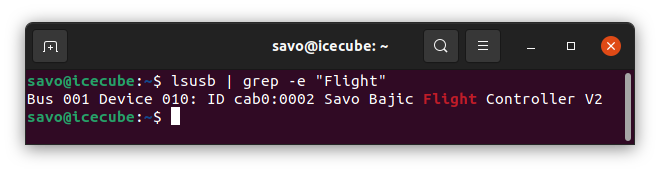
With all this set up and tested, I could confidently start working on uploading code to the board.
Barometer
The first sensor I set my eyes on programming a library for was the barometer, the BME280. This was because I saw it as the simpler and thus easier one to work with compared to the IMU since I only needed a couple of data fields from it. I wanted to see the effort needed to make the sort of library I was used to just importing from other people.
Since I was communicating with it over I2C I built my library on top of the existing Arduino I2C library, with wrapper functions used to configure and communicate with it. These were successful and I was able to monitor the pressure in my room and see it change as I waved the board about. There seems to be a nissue currently where the readings seem to bounce a fair bit even when the board is held still, hopefully I can resolve this with some more code.
Next Steps
My next steps for the project are roughly:
- Finish the barometer library (or use someone else’s)
- Prepare a library for the IMU (or find an existing one)
- Prepare a sensor loop on the STM32 to monitor the drone state from the sensors
- Develop and test the communication protocol for the nRF24 modules
- Start messing with ESCs (might be swapped with 4, we’ll see)