Flight Controller V2
Page Last Updated: January 5, 2025
Status: Development on hold for ESCs
Started: May 2020
My more powerful STM32 based version of a flight controller. Currently on hold.
As part of my project to make a quadcopter from scratch I need a flight controller to control it in flight and receive instructions from me. Overall this board would have four over responsibilities:
To achieve these, a microcontroller was put on a board as well as the basic sensors needed for a drone (accelerometer and gyroscope) with breakouts to connect to the ESCs and the radio module.
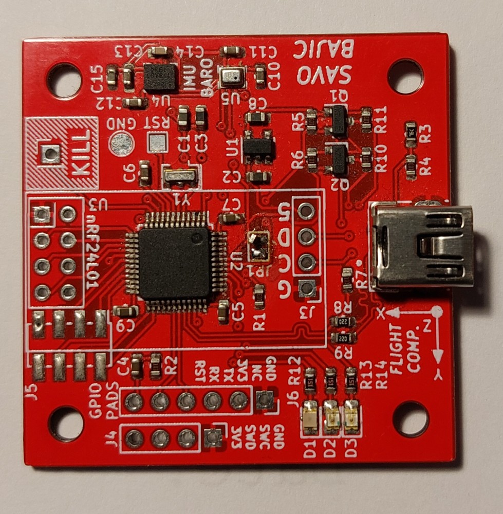
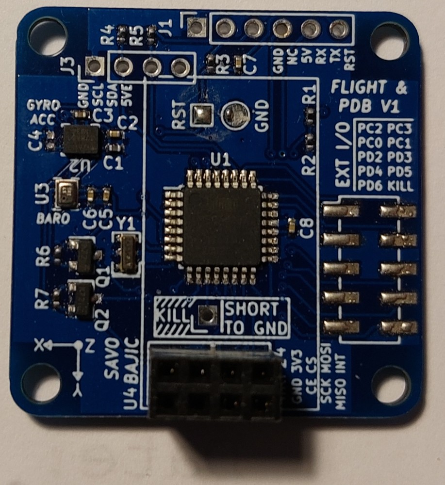
There are two main revisions, the original ATmega328P based one, and a second STM32F103 based one.
I intend to write as much of the code related to the drone controls as I can, although I am prepared to revert to an established open-source standard such as BetaFlight and the like.
Although I have prepared the boards and done some basic tests, I plan to leave off most of the coding until I have functioning ESCs to allow the drone to fly and better test control systems.
Not too many so far really, other than the benefits of using a proper IDE for larger projects.
Will probably have more once I get coding them properly.
The brain of a drone is generally called a flight controller and a drone is little more than four stupidly powerful motors attached to a minuscule frame without one. This flight controller is responsible for not only receiving commands from the pilot but also stabilizing the drone given feedback from sensors, namely Inertial Measurement Units (IMU) that keep track of the accelerations the drone experiences and thus can be used to construct an idea of the drone’s orientation and speed.
Although there are commercial flight controllers available on the market I wanted to try my hand at making one from scratch to see the effort that goes into it, as well as allowing myself to tailor it to my desires, most notably digital control of the ESCs. I would also like to retain flexibility for future uses such as a fixed wing aircraft.
So far I have made two similar versions, save the microcontroller at the heart of them. I am primarily focusing my efforts on developing the second one as it has the more capable microcontroller so I should be able to get more out of it in the long run.
I intend to try and code them entirely, although I may likely make concessions to using publicly available libraries to interface with the modules in the system so I may focus on the more application specific aspects of coding. I am also aware of projects such as ArduPilot and BetaFlight that I could try to get working on my flight controller to simplify the development process if I find it too difficult.
Although each revision is based around a different microcontroller, the majority of the systems around them are the same across versions.
Both boards have built in linear regulators to generate the voltages needed to run the microcontroller and the sensors on board. They also both carry banks of decoupling capacitors for the regulator and most integrated circuits present.
The method of communication I intend to use on these boards is digital communication at 2.4 GHz provided by standalone nRF24L01 modules from Nordic Semiconductors. These house all the radio black magic on a separate board that is interacted with over SPI from the main microcontroller. I gained familiarity with these from my telemetry work for HPVDT. In addition to the SPI pins shared between the microcontroller and the module, there is a line used to flag the flight controller of a received transmission which I have prepared to be used as an interrupt on the flight controller.
These modules I have purchased are rated for low bandwidth (~100 kb/s) at ranges of around 1 km with direct line of sight. This is good for me as I intend to operate this drone (for now) exclusively with direct line of sight and up to a few hundred meters at most.
There are two primary sensors ICs on each board use I2C to communicate with the microcontroller. They are the IMU and barometer. This I2C bus needs to be operated at 3.3 V since both chips operate at this level. This requires a level shifter from the 5 V I2C bus for the ESC to these.
The boards use the same inertial measurement unit, an ICM-20600 which monitors six axes of motion: linear and rotational acceleration around the three Cartesian axes (X, Y, Z) relative to the IC. They are capable of monitoring ±16 G of acceleration and ±2000 °/sec of rotation at their full scale, but this can be decreased in exchange for improved accuracy in the measurements.
These will be used to help the drone deduce its current orientation based on the integrals of these readings.
Each board has a barometer designed into it, the BMP280 which is used to monitor the ambient pressure and thus help estimate the altitude of the drone so it can maintain it. It is accurate to under a meter and lower with the right algorithms so it will hopefully be helpful when navigated closed spaces.
In the interest of keeping my design flexible for future use I have broken out many of the otherwise unused pins on my microcontrollers to headers that I can easily connect to later. For example I could use these to control lights on my drone(s) or actuators.
I left headers for the microcontrollers to be easily programmed using their designated protocols as well as the using the standard Arduino-esque bootloader and USB to Serial adapter which is handy for sending detailed debugging data to the controller even when not used for programming.
Below is a list of my different versions of my flight boards. Their logs will contain the information specific to them such as my motivation for making them as I did and the differing hardware.

Page Last Updated: January 5, 2025
Status: Development on hold for ESCs
Started: May 2020
My more powerful STM32 based version of a flight controller. Currently on hold.

Page Last Updated: January 5, 2025
Status: Assembled. Not planning on using.
Period: May 2020 - May 2020
My first flight controller design. Based on an ATmega328P so I could adapt many open-source drone projects to it if needed.