Flight Controller V1
Table of Contents
Overview
My first design of a flight controller for my custom drone, based principally around and ATmega328P so it could be easily adapted to use open source efforts in drone control like ArduPilot which are based around common hobbyist chips like this one (from the Arduino Uno and Nano).
The hardware design was pretty simple and I had no issues with assembly and passing basic tests.
I have not yet bothered to code for this as it is a back up to the more powerful V2 which I have not needed to give up on.
Requirements
In addition to the general ones outlined for all flight controllers:
- Use the ATmega328P microcontroller as the heart of the system
Takeaways
- Was a built in voltage regulator necessary?
Detailed Report
This was my first attempt to make a flight computer, unlike the ESC where I started working off someone else’s design, I truly started from scratch here, other than using the standard ATmega328P setup for Arduinos. I decided to base this one around that specific microcontroller to ensure greater compatibility with other efforts in flight controller software if I eventually tried to use them instead of potentially having to port their code to the less common STM32.
The hardware side of designing this was simpler than expected once I had selected my sensors, since I was basically just slapping together three ICs and some voltage regulators on an board. There were no considerations needed for high power or transients beyond decoupling capacitors because it was a low power board.
The real meat of this project would be the code. However I never intended to focus on the development of this board since it is meant to be a backup to the more powerful V2. So beyond verifying everything worked as intended on the board, I never bothered to code for it.
Circuit Design
Since the main purpose of this board is to shuffle around data I made sure to prioritize the hardware bus pins on the ATmega328P for this purpose. Other than that there honestly weren’t too many design choices I needed to make beyond selecting my exact ICs for each purpose since I simply used the recommended reference design for each segment of the circuit.
The only exception being the level shifter, which although a standard reference design, I needed to select the exact MOSFETs to use for the job.

There isn’t much unique electronically about this board compared to the outline I had for the the flight controllers in general.
Layout
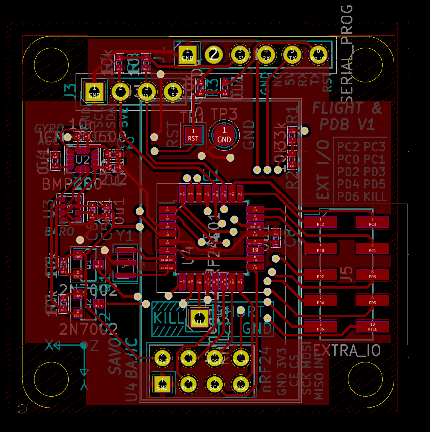
The layout of this board was done on a two layered, 36mm by 36mm board. Much like the layout of the first ESC I had one side focused on all the control electronics and the other where all the power related electronics resided. I had placed mounting holes in the corners to fasten it properly to the drone.
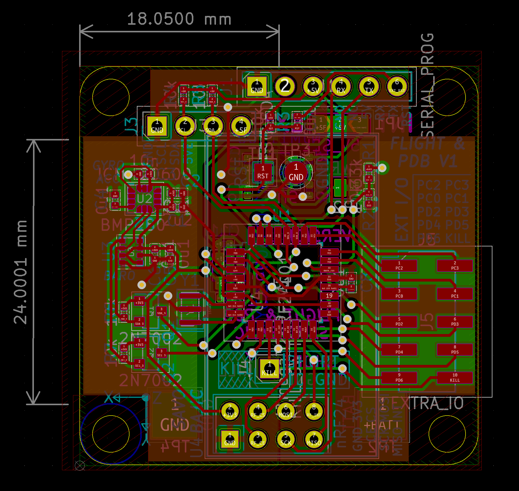
For the control side I figured that placing the ATmega in the centre would help ease routing so most traces would fan out of it and thus less wonky routing would be needed. Along the left is where the sensors sit, the bottom is the connection to the nRF24 module, the right has the spare inputs/outputs, and the top has the headers for programming and I2C for the ESCs.
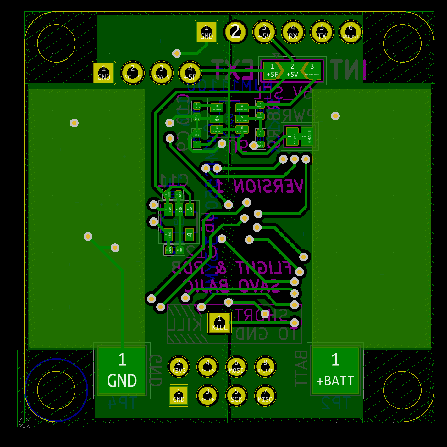
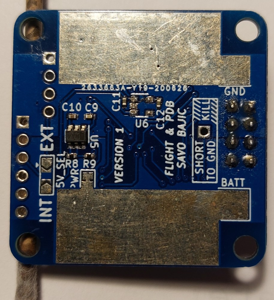
The rear is where the pours were made for the ESCs to tap into the battery power from a common bus. Sandwiched between these pours were the two dedicated voltage regulators for the board producing 5V and 3.3V with moderate current capacity so no need for thick traces.
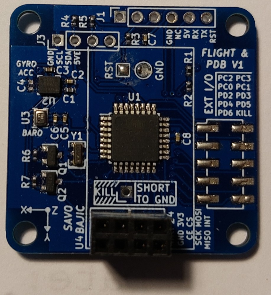
Assembly
Assembly was simple and I faced no issues.
Testing
I checked for shorts between adjacent pins with a multimeter as well as power lines, then I applied power and verified that the regulators were also working as expected, producing a steady 5 V and 3.3 V. I then left the system powered for a few minutes to monitor current draw and ensure none of the ICs were getting warm, which they didn’t.
After the basic power tests were done I was able to burn the bootloader on the ATmega328P to program it over Serial like a normal Arduino without issue. Other than a basic I2C bus scan to check the sensors were responsive, nothing has been done with the board.