ESC V1
Table of Contents
Overview
I decided to try and make my own quad-rotor drone from scratch to give myself a large project. One component of this is to make the Electronic Speed Controller (ESC) used for the rotors.
This design is based on ELECTRONOOB’s work with his open-source ESC. This first version of my ESC was basically a replica of his work.
Although I designed the system and [almost] assembled a board, I never actually did anything with them beyond that because it was just a warm up for my second version and beyond.
Takeaways
- This board was quite large and would barely fit on the frame I ordered. So I needed to shrink it down.
Detailed Report
I was looking for an interesting project to bite into that would be both fun for me and cool to show off, even to non-technically inclined people (such as my mother), so I decided to try and make my own quad-rotor drone from scratch. As many would have you believe, the motors need to be accurately controlled for it to stay in the air.
Circuit Design
I started this design based on ELECTRONOOB’s work with his first ESC but primarily his third version. This first version of my ESC was largely a replica of his work, with only a few tweaks related to the MOSFETs and the driver I selected.
The circuit design was basically taken from his first version, with the modifications made to basically feature match his third version. This meant removing the parts related to the USB and the buzzer. In addition some parts relating to the MOSFETs were changed to ones I could readily find.

Brains
The heart of the system is the ATmega328P, in the TQFP-32 form of Arduino Nano fame. This chip is responsible for all the control of the system, it will receive commands over PWM or I2C and direct the MOSFET driver accordingly. It is also used for detecting the zero-crossings using the internal comparator and some external resistor arrays to divide the voltages from the motors down to a safe level for the Atmega328P as well as averaging them for a “zero”. It is configured to be programmable using a generic serial programmer from the like of FTDI like a normal Arduino Nano.
There are a set of solder jumpers to be used to configure the ESC without needing to reprogram it: the default rotation can be reversed with a jumper, and the I2C address the ATmega will take.
Inverter (Motor Control)
Motor control is handed by a three phase inverter made of TPN2R903PL N-channel MOSFETs, driven by a single FAN7888 MOSFET driver IC that receives control signals from the ATmega.
N-channel MOSFETs are used on both sides of the bridge due to their lower “on” resistance. To drive the high-side FETs requires “bootstrapping” to get a gate voltage higher than the drain (VBAT) for optimal performance. This process is handled by the FAN7888 and a capacitor and diode for each phase (D1-D3, C2-C4), resistors are recommended but not required (RN3).
Bootstrapping in this application is the process of changing a capacitor between ground and the supply voltage, then disconnecting it on both ends. Then connecting the capacitor terminal that was previously connected to ground, to the supply rail. Since the potential across the capacitor has not been changed, the potential at the positive side is now twice that of the supply rail relative to ground. This is then routed to drive the gate of the high side MOSFETs. The FAN7888 does not actually switch the connections on the low side of the bootstrapping capacitor, it has that constantly connected to the source of the MOSFETs (phase output), but it achieves the same effect and is useful for a few other reasons such as avoiding potentially exceeding the gate-source voltage.
5 V Regulator (Battery Elimination Circuit)
A 5 V buck regulator is used to supply the microcontroller with power from the battery input. Although the individual draw of the microcontroller on the ESC is well within what could be reasonably provided by a linear regulator, thus saving space on the board and reducing system cost, I decided to use the buck regulator to allow the 5 V from an ESC to be used as a common rail to efficiently power other drone systems instead having to design a 5 V regulator into each.
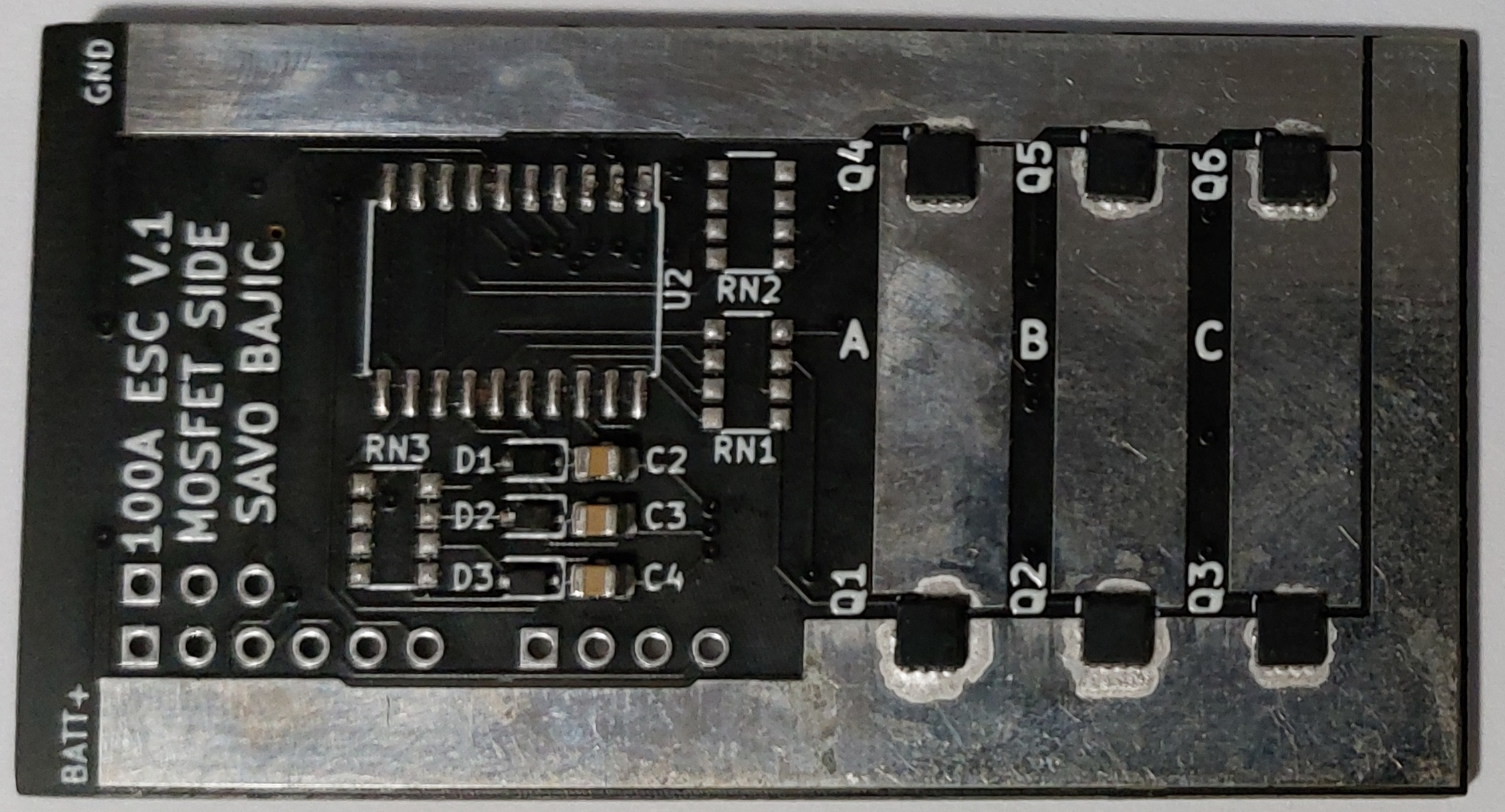
Board Layout
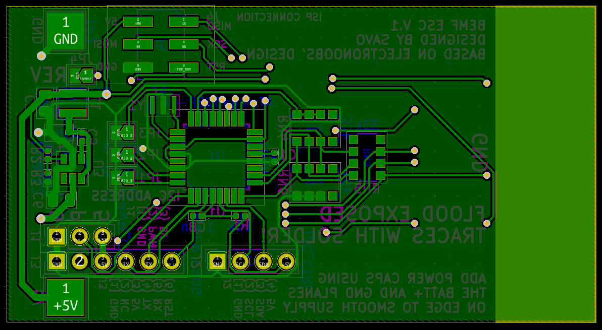
I laid out the circuit on a board that I arbitrarily set to be 65 by 35 mm. In order to decrease the size I had the output stage of the circuit on one side and the remainder of the electronics on the other. All power lines are t be soldered on their designated pads/exposed traces. Along the right edge of the figures there is a large exposed pad for the two power rails, this was done to easily allow the soldering of buffer capacitors along this edge as needed.
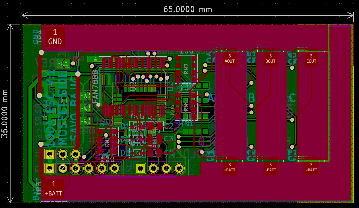
The output stage was put all on one side for simplicity and because given the powerful nature of the components, they were generally bulkier, as well as the traces. I designed all the power traces to be 5 mm wide to carry upwards of 10 A without exceeding a 20 °C rise in temperature with 1 oz. copper (~35 um) (on the drone they will be positioned under the propellors which should aid with cooling. In addition to their width, I exposed the power traces to allow easier soldering of wires to them as well flooding them with solder to increase their current capacities.
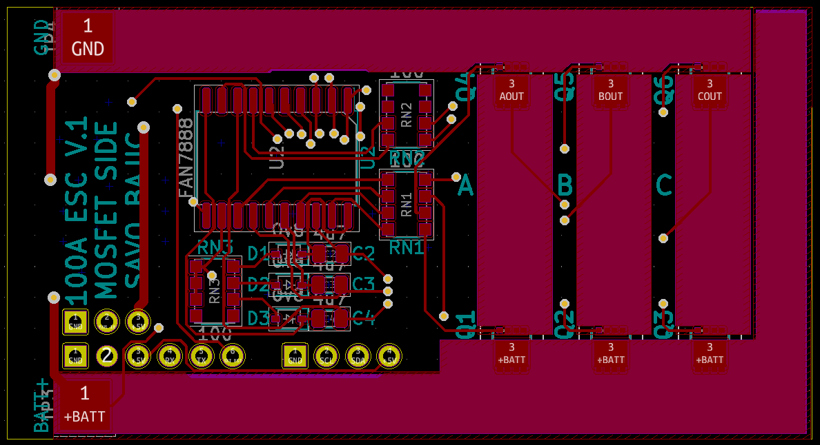
The remainder of the system (control and voltage regulator) were housed on one shared side. The 5 V buck regulator was nested between the ground and +5 V pads on the left part of the board, with distinct thicker traces for the power into and out of it to carry the up to 1 A at 5 V without issue. The remainder of the side was used for the control part of the system.
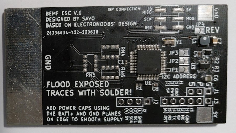
Assembly
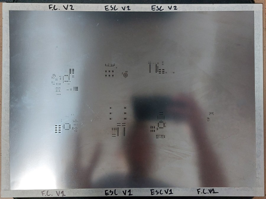
Assembly wasn’t too notable, other than being my first set of SMT board to have components on both sides. This required me to prop up the edges of the board so it would not be resting on the components and be level for when I was applying the solder paste using the stencil. Since I was ordering and assembling V1 and V2 of the ESCs and Flight Computers together, I ordered a stencil that had a portion for each of them.
One thing I did mess up during assembly is when ordering the resistor arrays I accidentally ordered the wrong size - twice. This is partially why I never tested these boards, although I could have easily fit through-hole resistors in their place like I did with my gameBOI.