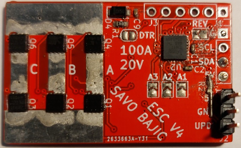
ESC V5
Page Last Updated: January 5, 2025
Status: Complete. Revision needed.
Period: August 2021 - April 2022
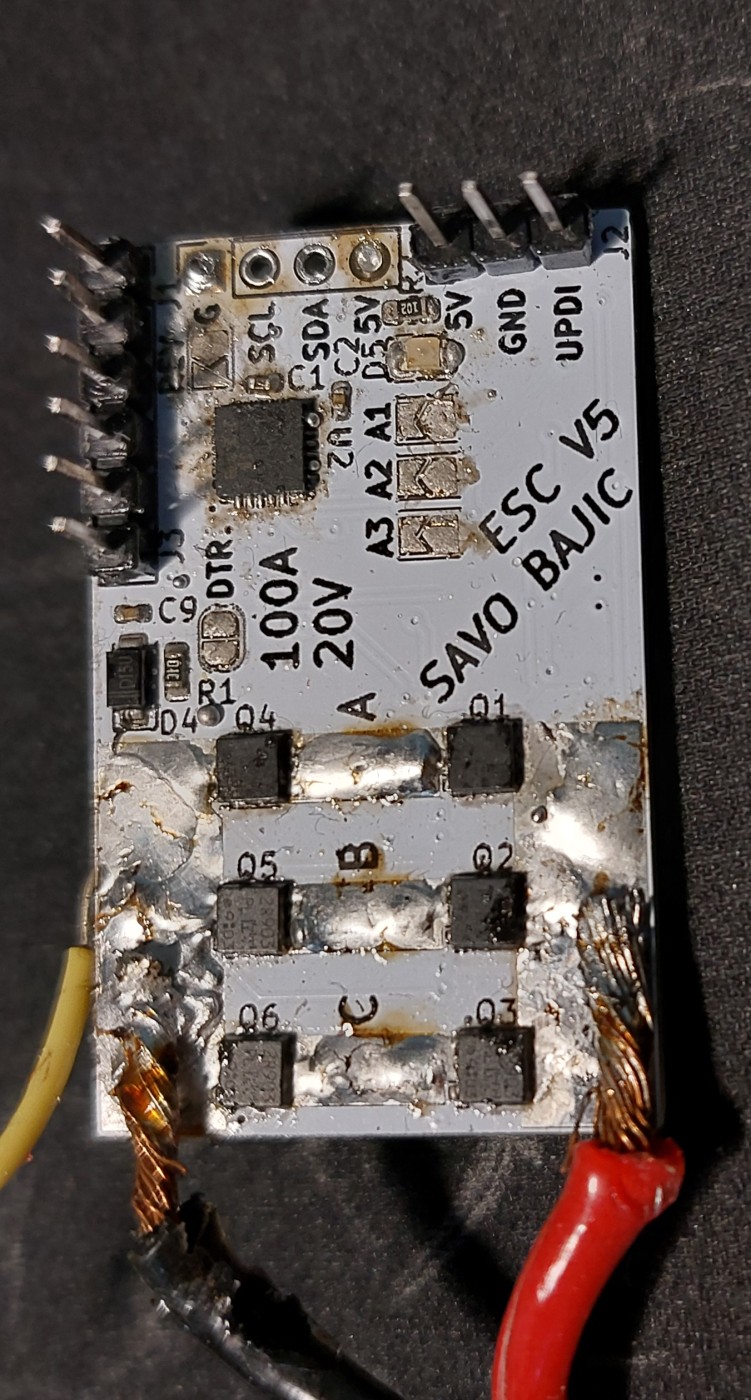
Newest revision to the ESC. Largely designed to use the available MOSFET drivers.
I decided to try and make my own quad-rotor drone from scratch to give myself a large project. One component of this is to make the Electronic Speed Controller (ESC) used for the each rotor’s motor.
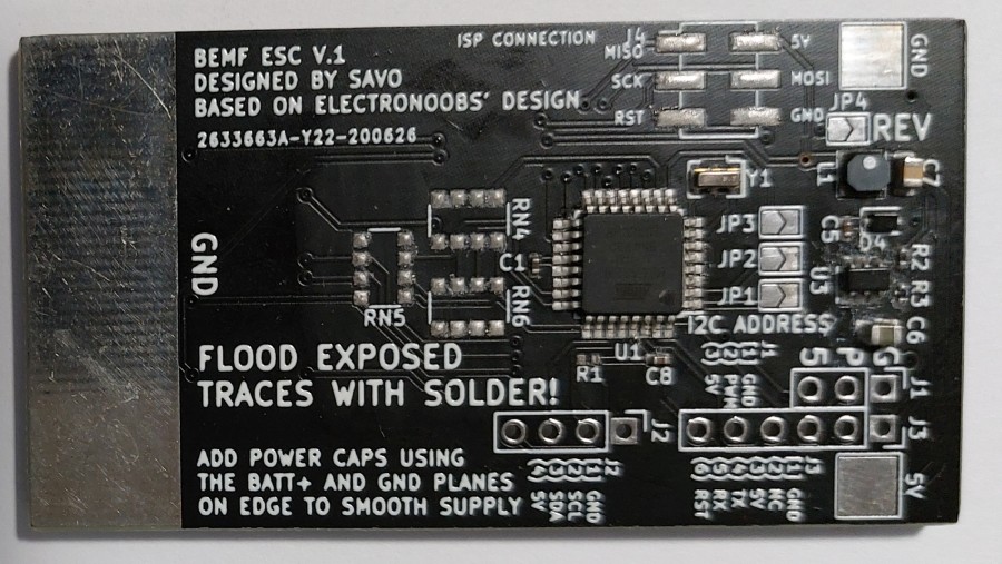
My designs were originally based on ELECTRONOOB’s work with his open-source ESC. This first three versions of my ESC was basically a replica of his hardware. With the fourth onward, the hardware is completely my own.
Most of my software development for features was done with my second version. Initially I intended to use ELECTRONOOB’s code however I needed to change it to match my hardware design and I noticed it wasn’t commuting the motor correctly, so I ultimately decided to re-write most of it from scratch.
When I moved to my fourth revision I needed to re-write much of my code again because I made extensive use of hardware and registers that were different between the two microcontrollers.
Current Status: I am able to control small motors with the fifth version! However larger motors damage and eventually destroy my boards so I am redesigning my circuit to be able to handle the stresses imposed by larger motors.
Although I wouldn’t describe myself a great teacher, I will try my best to provide a basic overview of brush-less DC motor control theory.
An electric motor generally uses a set of permanent magnets and electrified coils to generate rotary motion. As current flows through a coil, a magnetic field is generated, this magnetic field will induce a force (torque) on the coil as it tries to align itself with the ambient magnetic field produced by the permanent magnets. Just before the fields reach alignment (and thus no more force will be imparted on the motor), the current is commutated so the fields generated are no longer about to align and the force continues to be imparted on the motor shaft. This cycle repeats as long as the motor is operating. The rotating assemble in the motor is called the rotor, the stationary assembly the stator.
Basic DC motors use mechanical commutation methods like the brushes in the animation above. The motors used in most quad-copters, especially for high performance drones, are brush-less DC motors which are constructed differently and need a special controller to operate properly, generally called Electronic Speed Controllers (ESC). Their more complicated operation is a trade off for significantly increased power density, vital for flight.
Instead of having the coils attached to the rotating shaft to induce force on it due to the fixed ambient field from the permanent magnets, they reverse this setup and have the motors on the shaft and windings stationary. Thus no brushes are present and the motors are instead controlled using a three phase scheme. To do this the voltage on one of the wires must pulled low, and high on another, while the third one is disconnected from either extreme. The supply of power must be quickly and reliably changed to generate the needed rotation. This supply of power and commutation timing is what is handled by the ESC.
Since most motors used on drones are meant to be compact and cheap, they usually lack any sensors on them to aid the controller in properly knowing the position of the rotor, thus when it is optimal to commutate. However, there is a trick that can be employed to derive the position of the rotor! Due to the generally rapid rotation of the rotor, there is a back electro-motive force (BEMF) exerted on the coils in the stator, which can be monitored using the disconnected phase of the motor.
When disconnected from power the voltage on a phase will start at the voltage it was last supplied, as the rotor rotates the voltage will gradually change to approach the other extreme at which point it will need to switch to that supply.
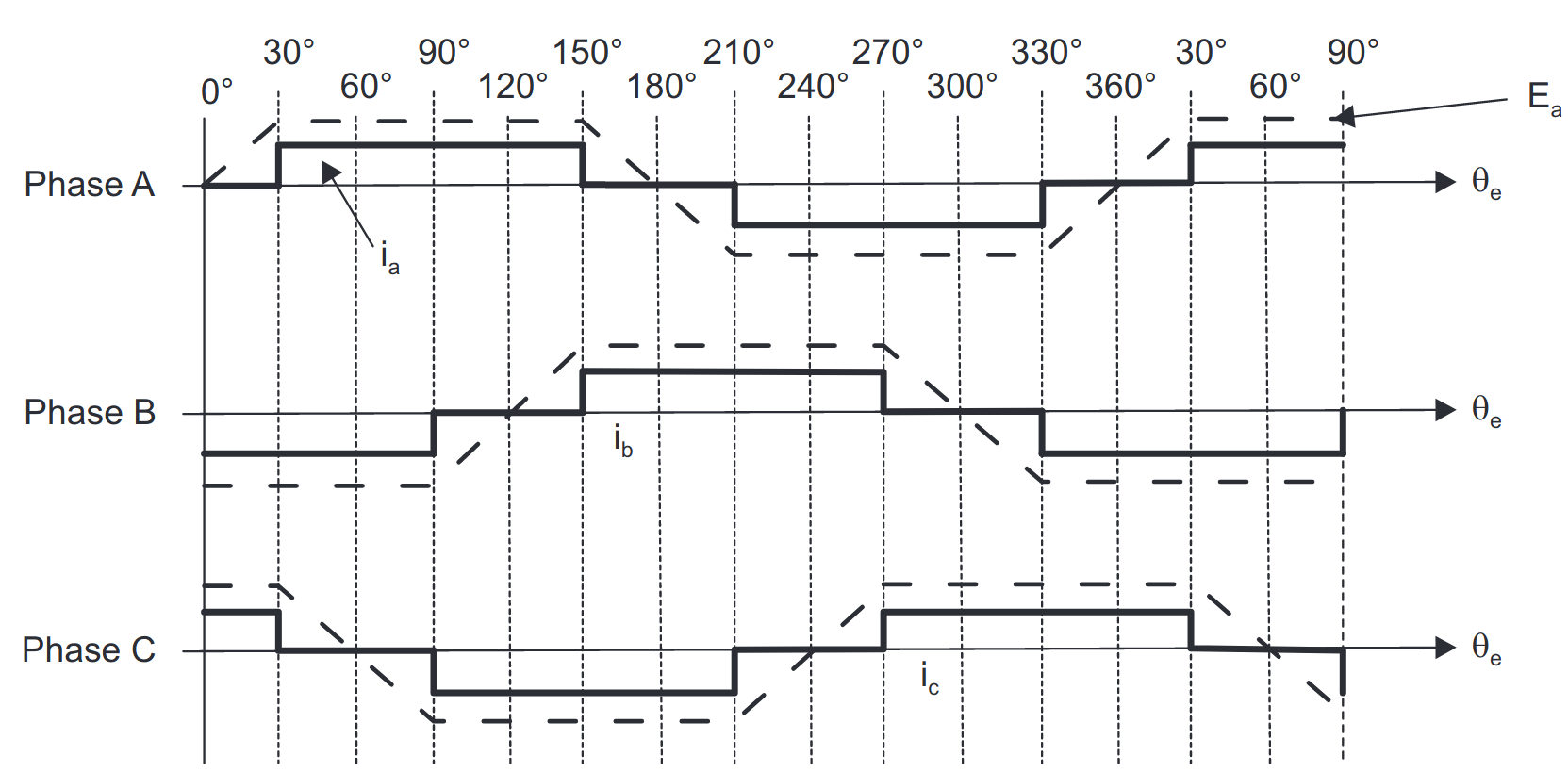
One generally finds it easiest to use the moment the voltage on this disconnected phase crosses the average voltage of all phases (also called the “zero” voltage) using a comparator to know when the rotor is halfway through the step and time the next commutation based on the time elapsed since the most recent phase change to reach that midpoint-crossing.
This project has been very iterative, and I have made a page for each revision to explain the intent of it and details related to it the main ones of interest being V2 and V4.
Page Last Updated: January 5, 2025
Status: Complete. Revision needed.
Period: August 2021 - April 2022
Newest revision to the ESC. Largely designed to use the available MOSFET drivers.
Page Last Updated: January 5, 2025
Status: Revised. Ran out of parts for testing.
Period: September 2020 - August 2021
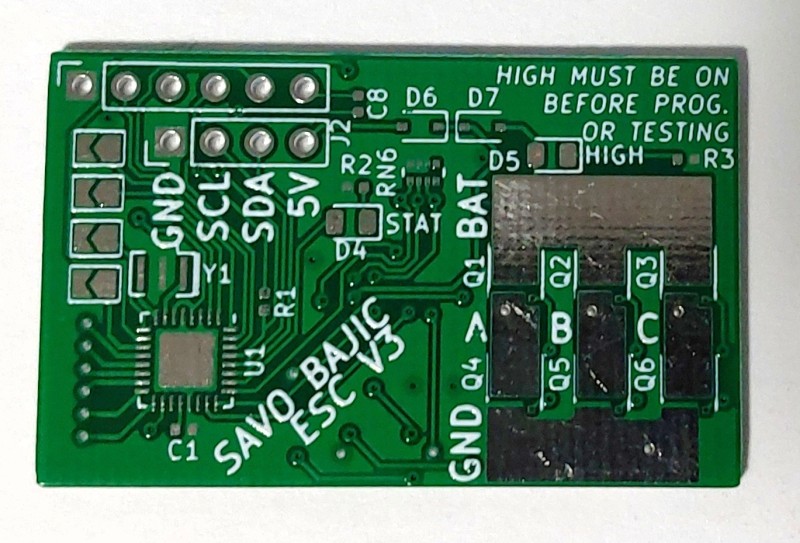
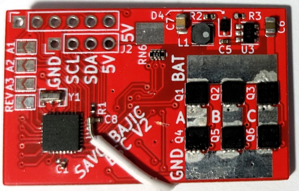
Another major revision to the BLDC ESC, mainly changing to the modern ATtiny family of microcontrollers.
Page Last Updated: January 5, 2025
Status: Completed design, never assembled
Period: August 2020 - September 2020
A revision of ESV V2 with the voltage regulator removed
Page Last Updated: January 5, 2025
Status: Complete
Period: May 2020 - September 2020
My first actual attempt at building an ESC. A shrunk down revision of the first.
Page Last Updated: January 5, 2025
Status: Assembled, Never Used
Period: May 2020 - May 2020
Tags: BLDC drone embedded ESC KiCAD
My first attempt to make a sensor-less ESC for my drone