ESC V5
Table of Contents
Overview
I needed a new revision of my ESC to accommodate the replacement MOSFET drivers I was able to source as my previous one was out of stock for the foreseeable future. I also used this as an opportunity to fix some of the minor inconveniences I faced with V4.
This version was successful, I dare say my first proper working ESC - even if a bit limited in some aspects (e.g. a high-ish lower limit on speed). The test motor ran perfectly within these limits, ESC and motor remaining in sync as the PWM duty was varied. The system responded to command over both I2C and PWM input. I was confident I was ready for the proper drone motors!
Issues quickly surfaced when I moved up to the larger and more powerful motor. It appears that the transients induced by the increased power were not well handled by my board: causing brownouts at best, and frying chips at worst. This however is a largely hardware problem so I don’t foresee much needing to change software wise to address this.
Takeaways
Overall I would say that this was a success. I had a complete working BEMF ESC working for smaller motors, which implies that most of the foundation (at least in software) is present for the larger motors. I will need to revise my hardware to accommodate the proper motors I intend to use as well as tweaking the weaker parts of software.
- Transients can really be a pain in the stinker
- More power, harsher transients
- Non-idealities in capacitor leads
- Switching noise / inductive kick back
- Using the decode function on my oscilloscope for UART debug messages was helpful since I check the reaction of the MCU using a single pin
- It might be worthwhile to investigate making more automated tests for basic functions such as output functions
Detailed Report
This revision was started because I had run out of functioning parts during the testing of V4 and the IC shortage has forced me to select an alternative MOSFET driver, the IRS2334S from International Rectifier as the replacement for the FAN7388s and FAN7888s I was using until then.
My goal is to keep the board as similar to V4 so that my code doesn’t have to be significantly altered and I can focus on getting the motors to work.
Circuit Design
Circuit design is basically the same as V4 with only a few minor changes.
- Replaced the FAN7388/FAN7888 MOSFET driver with the IRS2334S
- Removed the unnecessary resistor on the UDPI line (R2 in V4’s schematic)
- Rearranged the MOSFET driver signals such that all the low side signals are on one port. (Done to simplify/optimize coding for commutations)
- Added a status LED on the last unused pin

Layout
Laying out the board I wanted to try and keep the part placements identical to V4’s so I could reuse the same solder paste stencil, this is a major reason why I choose the IRS2334S since it came in the same package as the FAN7x88s. Other than the addition of the status LED, I was able to leave all components in their place and seat the new ones in place of removed ones (R2 where old R2 was, and the MOSFET drivers).
Routing traces was a bit harder than expected since I didn’t want to redo the entire thing from scratch. As a result, I spent a good portion of my routing seeing how close I could squeeze some traces and vias.
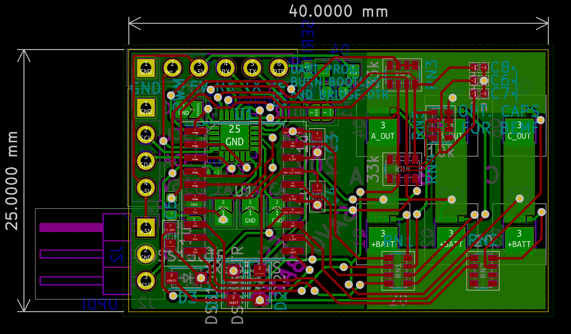
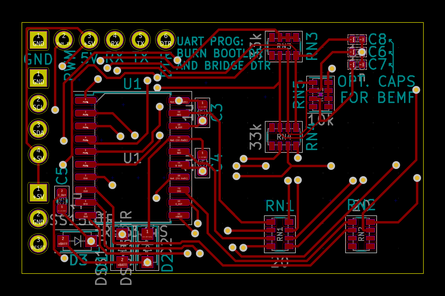
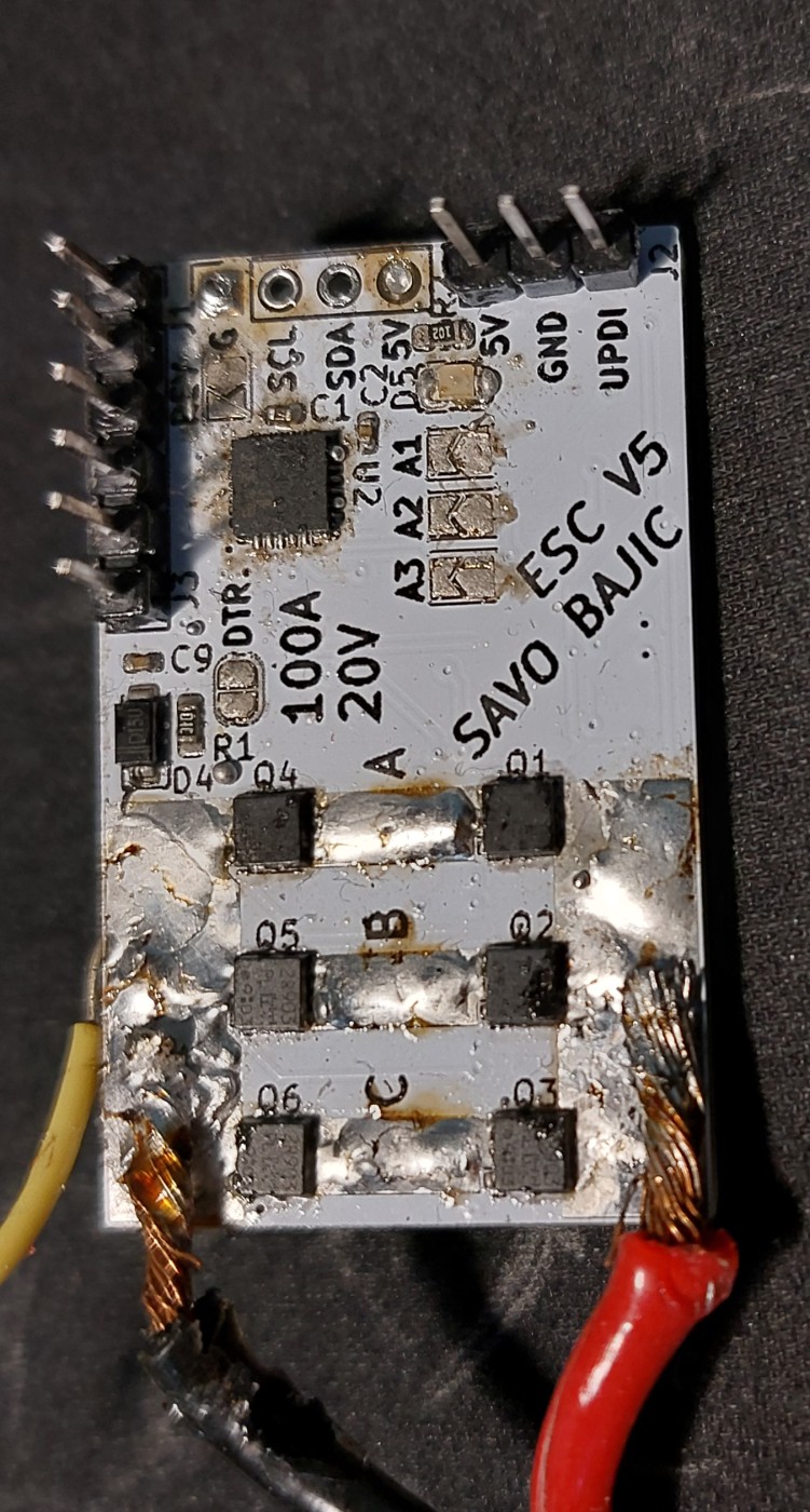
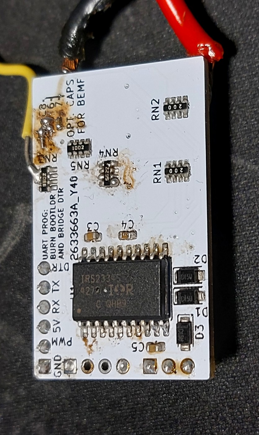
The top side of the board houses the MOSFET driver circuitry on the left half and the feedback network on the right.
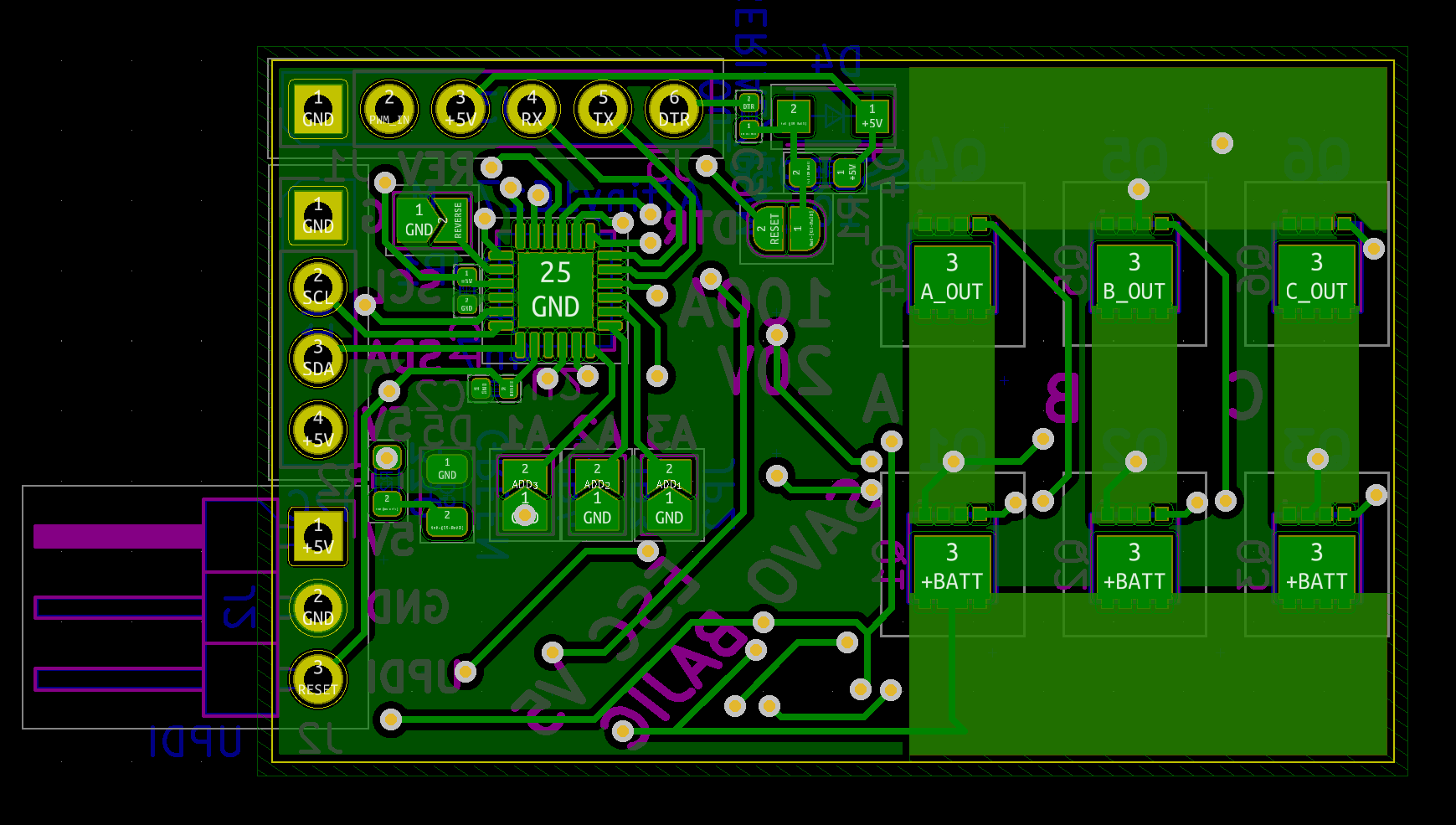
The bottom of the board is where the control section and MOSFETs are located. I added the status diode between the address pads and R2 on the left.
Assembly
I received the components and boards I needed, and started the assembly at the start of April. The final results came out pretty nicely. Unfortunately I didn’t think to take any nice photographs of it before I started to solder on the regulator I made for the drone, and then the bank of capacitors to try and handle the transients.
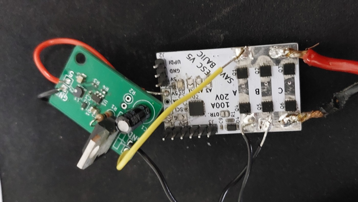
I took these photos after doing all my modifications, testing, and removing the capacitor banks so there is visible proof of these changes with the burn/flux marks on the boards. On the front the only real rework was adding/removing motor leads and capacitors.
On the bottom face of the board there was more rework, related to the modifications done to the BEMF feedback network. There is also a wire lead attached to RN3 along the top, which was used to probe the virtual zero of the motor.
Honestly speaking, the only real difference in the appearance of V5 from V4 is that I ordered it in a white solder mask with black silkscreen scheme, whereas V4 was red and white respectively. As explained in the layout section, the layout was intentional kept identical to V4.
Porting Code from V4
Since I kept the same microcontroller and largely the same pin allocations, I was able to quickly reuse most of the code I developed for V4. The only changes I had to accommodate was a minor shuffling of the motor control pins, and the new status LED.
The changes for the motor pins was just changing some of the masks used for changing the registers.
LED Library
For the LED I made a basic library of some boilerplate code; LEDSetup(), LEDOn(), LEDBlink(), etc. The most challenging aspect of this library was making a set of functions to allow for non-blocking blinking functionality. This was accomplished using one function (setNonBlockingBlink) that sets some global variables to the number of blinks desired and the period, then another (nonBlockingLEDBlink) that is called with each iteration of the main loop that checks these global variables and operates the LED.
void nonBlockingLEDBlink() {

  // Check if we are even blinking
  if (nonBlockTogglesLeft > 0) {

    // See if we have passed a point to blink
    if (nonBlockToggleTime < millis()) {

      LEDToggle();
      nonBlockToggleTime = millis() + nonBlockTogglePeriod;
      nonBlockTogglesLeft--;

      if (nonBlockTogglesLeft == 0) LEDOn(); // Turn on LED at finish
    }
  }
}

void setNonBlockingBlink (unsigned int period, unsigned int count) {
  LEDOff(); // Start with LED off

  nonBlockTogglesLeft = (count * 2) - 1;  // Two toggles per count, exclude starting one
  nonBlockTogglePeriod = period;

  nonBlockToggleTime = millis() + period; // Record next toggle time
}
With functionality matched with V4, I got cracking on implementing new features that I didn’t get to with V4.
Development
The rough outline of how features were developed for this version. I started with buzzing to try and remedy the issue V4 had with it before taking a swing at driving the motor since I [correctly] anticipated it would take longer and pose more of a challenge to me.
- Motor buzzing
- Get the motor to spin up
- Maintaining rotation (at full power)
- Without PWM I can focus on the zero-crossing detection system
- Modulating speed with PWM
- See how the PWM affects zero-crossing detection
Reminder: I had already managed to spin up and maintain a motor at full speed even with V2! V4 and V5 were supposed to allow me to modulate the speed of the motor with proper PWM. Since I was adding PWM I needed to retrace these steps to the PWM didn’t break my old approach/code for motor control.
Buzzing
This was what seemed to kill my MOSFET drivers on the V4s. After combing through the code for it I found that the allLow() function I was using failed to set all the phases low correctly. Once that was remedied, the motors buzzed as I commanded them to with my buzz() function that had remained largely unchanged since V2, other than pin allocations being updated to match each board.
The flow of this function was to take in two arguments for the the period of the buzz, and the duration to buzz; in micro- and milliseconds respectively. It would check that the motor wasn’t already spinning, constrain the arguments between some limits I set, and then actually buzz. Buzzing is achieved by energizing coils for a very brief period of time and alternating between two steps at the period requested to produce noise.
Below is how the function roughly looks in code.
// Buzzer function.
void buzz(int periodMicros, int durationMillis) {

  if (motorStatus) return; // Will not run if motor is enabled and spinning.
  // It would [greatly] suck if the drone "buzzed" mid-flight

  // Ensure period is in allowed tolerances
  periodMicros = constrain(periodMicros, minBuzzPeriod, maxBuzzPeriod);

  const unsigned int holdOn = 10;                         // Time the motor is pulled high (microseconds)
  int holdOff = (periodMicros / 2) - holdOn;              // Gets this holdoff period
  unsigned long endOfBuzzing = millis() + durationMillis; // Marks endpoint

  // Buzz until the endpoint
  while (millis() < endOfBuzzing) {
    // Clear the state of all pins so only the phases of interest are driven
    PORTA.OUTCLR = PIN5_bm;
    PORTC.OUTCLR = PIN3_bm | PIN4_bm;
    PORTB.OUTCLR = PIN0_bm | PIN1_bm | PIN5_bm;

    // Set the phases of interest
    PORTA.OUTSET = PIN5_bm; // A high
    PORTB.OUTSET = PIN1_bm; // B low
    delayMicroseconds(holdOn);
    allLow();
    delayMicroseconds(holdOff);

    ...
    (Repeat above but setting A high and C low)
    ...
  }
}
Spin Up
With buzzing sorted, I could get into the meat of the ESC, actually spinning a motor.
Since BEMF is proportional to the rotational speed of the motor, there is none available for feedback when the motor is started. For this reason the motor needs to be spun up using a different control scheme than what is used to maintain rotation. The method I have used since V2 is an open-loop approach where I manually commute the motor using a gradually decreasing period between steps until I hand it off to the zero-crossing system for usual operation.
This approach worked in my tests. I initially had some issues since I use the PWM peripheral to drive the high sides, however I failed to properly start the PWM peripheral before wind up as part of my motor enabling process. This was not an issue for my low sides since they are directly driven like normal digital outputs.
Once I ironed out the issue with PWM I had the motor successfully spinning up and I was ready to engage the task of maintaining rotation.
Maintaining Rotation
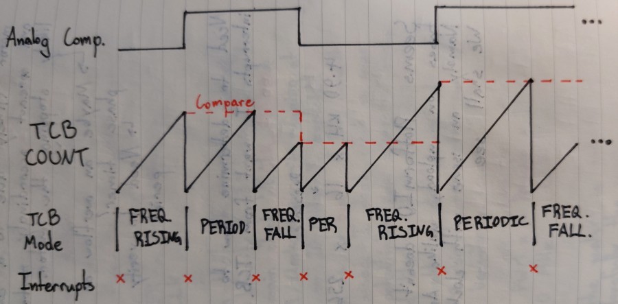
This section of code was prepared as part of V4 (see the zero-crossing and commutation sections) but never tested since I wanted to properly develop buzzing first, which prevented me from every reaching this stage. The essence of this code was to use the analog comparator to detect the zero-crossings and a timer that alternates between recording the time between these crossings and commuting the motor. I prepared a rough diagram showing these two working together.
As expected, my initial attempt at coding this (from V4) arguably complicated behaviour did not survive contact with reality. The motor would simply start to seize and sputter back and forth soon after exiting spin up. I bypassed the resistors put in series with each phase and added some smoothing capacitors to deal with the larger inrush current and the voltage drop it induced. The problem still persisted though.
Focusing on the Interrupts
Seeing that the motor was sputtering, my first suspect was that the interrupts needed to commute the motor were misfiring since it was the only new code introduced/changed since V2 which worked.
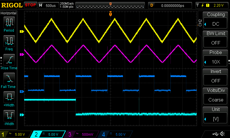
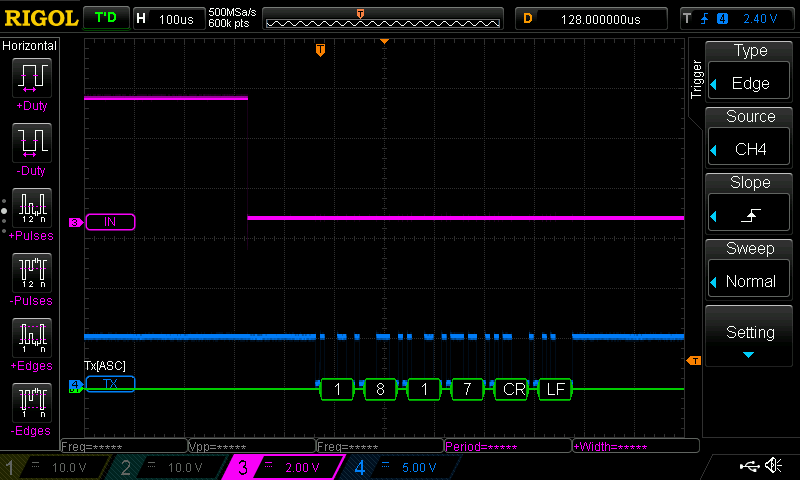
To investigate the interrupts I stripped back their duties from commuting the motor, to simply toggling the state of pins I was monitoring with my oscilloscope. To simulate the rising and falling edges of BEMF without a motor attached I used a triangle wave from my function generator and tied the other phases to high and low so that there would be a realistic “zero” point.
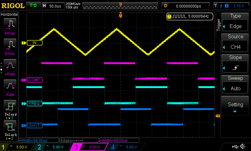
For my first test I simply had the timer toggle a pin every time its interrupt was run. This meant it should have resulted in a square wave with a frequency twice that of the triangle wave (one switch at the midpoint for capturing the zero crossing then another at the peak/trough for the delay from the zero crossing). However, it didn’t fire at all as shown in this figure.
Note: For the next few figures the legend for the different signals/waves is:
Wave 1 (yellow) - Raw input triangle wave
Wave 2 (cyan) - Output pin for the interrupt
Wave 3 (purple) - Zero point voltage
Wave 4 (blue) - Analog comparator output
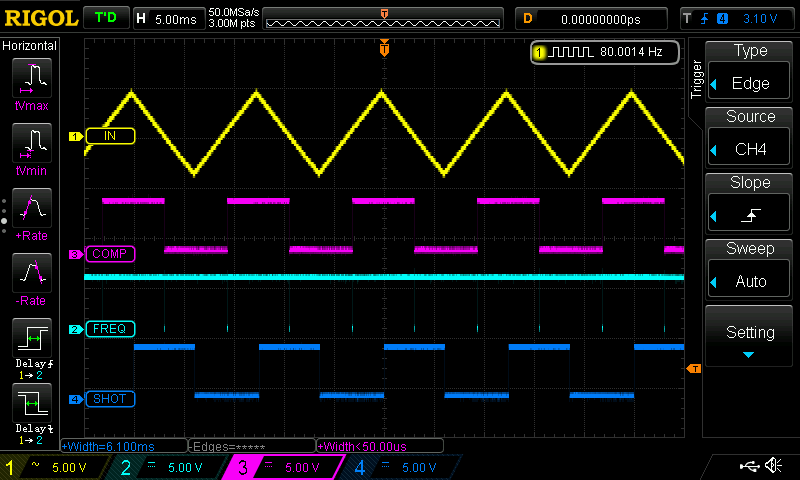
I did some tinkering to see where the issues might have been. I suspected that there might have been some noise around the crossing of the zero-point resulting in multiple crossings being falsely measured. To see if this was the case I had the interrupt just run in frequency/period capture mode and set the pin high if the recorded period exceeded a threshold, low otherwise. When I was feeding it a wave with a period smaller than the threshold it worked fine. However once I exceeded it, it became clear that there were these spurious switches since the output pin was going high and low, not staying high.
In the figure below you can see that towards the right there is a small peak on the output wave that perfectly illustrates this. It detects that the period since the last switch exceeded the threshold so the pin is set high. However there is noise so there is another switch event almost immediately afterwards that is caught and recorded so the pin is set low again since the time since the last change was less than the threshold.
Increasing the hysteresis on the comparator and adding digital filtering on the event fixed this issue for the period measurement.
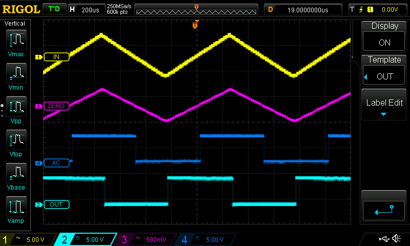
What remained was to then use this proper period to then commute the motor, by waiting the time equal to a half period to commutate. Originally I had intended to switch the mode of the timer between period capture and delayed event. When I tried this out in code I quickly ran into issues. The main one being its poor response to a changing (especially shortening) commutation period. My solution to this was to split the task across two timers, one to capture step periods, the other to solely commutate after a certain delay. This approach worked flawlessly, I was generating commutation events exactly out of phase with the zero-crossings as needed (matching the extremes of the input wave). This is shown in the figure below with the toggling of the output pin.
Driving Issue
Once I reworked the interrupts to commutate the motor instead of just toggling pins I found the motor was still struggling to rotate. The voltages on the phases was a mess after wind up.
Analyzing the output of the phases, I found it odd that phase A never seemed to be pulled low. So I set the ESC to simply through the six commutation cycle function calls in order (e.g. AHBL() for A high, B low). This return to basics would show me if my driving functions were working correctly or not.
Looking at this it was immediately obvious that A being held high when it should have been pulled low. I fixed the functions and the motor ran better but not perfectly yet. The phase changes don’t appear to be properly handled all the time.
PWM Modulation
I felt that I had reached far enough with the system operating at full power, so I began to start delving into tweaking the PWM system and trying it out.
Extending the Measurement Period
The timers used for period capture and commutation are type B timer/counters (TCBx), the timer used for PWM is type A (TCA0). TCBs are 16-bit meaning that they can count up to 65535, which at the ATtiny’s 20 MHz internal clock would mean that they can count to about 3.3 ms before they overflow, which limits the ESC to commutating at rates no lower than 300 Hz or about 25 rotations a second for a typical 12 winding motor. I was worried that this would not be a long enough of a period for slower spinning motors, especially when throttled, so I worked to extend this.
The TCB’s were both originally set to run off the clock signal for TCA because their pre-scaling is limited compared to that which TCA can (TCB’s can only run directly off the core clock, TCA’s clock, or halve the core clock). This way I could pre-scale the 20 MHz the ATtiny was running on down to a frequency that would allow TCB’s to observe longer events. The drawback of this was that the PWM period would be proportionally extended and thus be more perceptible for the feedback network for BEMF.
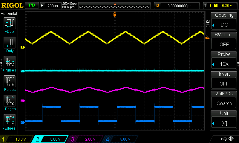
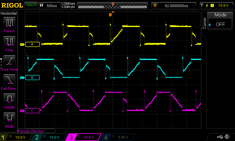
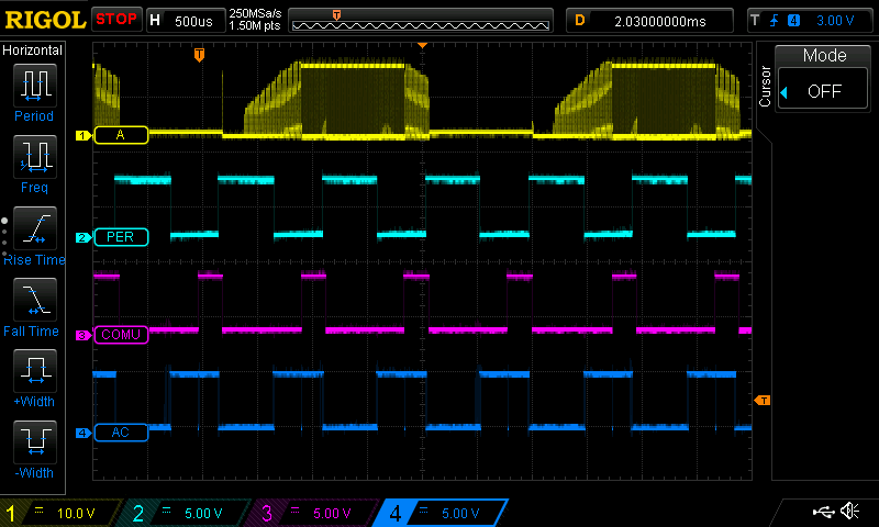
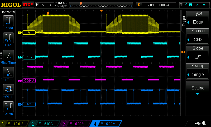
Below is a figure of the output across the phases with TCA prescaled by a factor of 8 down to 2.5 MHz. The PWM width is set to 254 of 255. This allows TCBs to measure periods up to 26 ms long! An effective RPM of as low 190, just over three rotations a second.
After some experimenting I decided to return TCA to run with no prescaler (20 MHz) resulting in a PWM square wave with a frequency of about 80 kHz. Instead the TCB’s would run off the halved core clock, at 10 MHz, so they will rollover ever 6.5 ms. This was an improvement for the PWM as I needed less filtering in the BEMF, however it meant that TCBs were limited to 6.5 ms before rolling over, still twice as long as the default but not great.
To get around this I made a little work around in software. Since the commutation timer (TCB1) goes off generally halfway through the period between two zero-crossings, I have it record the current count in the zero-crossing period timer (TCB0). Then when the zero-crossing is reached a simple check is performed to deduce if a rollover occurred or not: if the recorded count at commutation is greater than the current count in TCB0, then a rollover is implied.
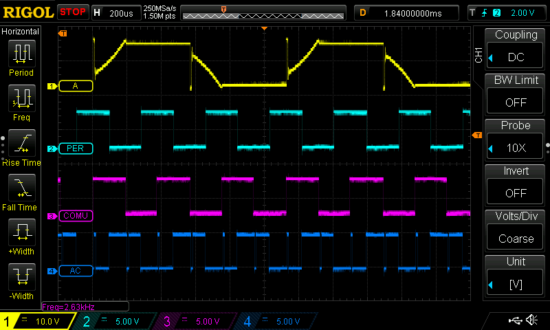
After some further testing this worked but would occasionally glitch, due to rapid switching around the zero crossing. This was addressed by me adding some software debouncing. The results were great! The system worked to reliably mark the commutation timing with simulated BEMF with step periods as low as 200 us to 16 ms, up to 22 ms but not as reliably too.
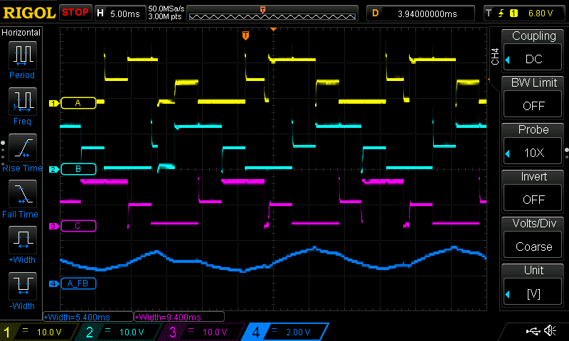
Note: For the next two figures the legend for the different signals/waves is:
Wave 1 (yellow) - Raw input triangle wave
Wave 2 (cyan) - Output for period measuring interrupt
Wave 3 (purple) - Analog comparator output
Wave 4 (blue) - Output for commutation interrupt (toggles on interrupt)
As shown, the commutations basically match the extremes of the simulated BEMF as needed for proper operation!
Changing BEMF Filter Capacitors
To smooth out these disturbances in the feedback system I changed the capacitors used, raising their values. However my math was off by an order of three, so I accidentally over-filtered the system at first with 1 uF.
After re-running the math, I returned to my initial design value of 1 nF which worked well to smooth out the PWM noise. Perhaps it could use a bit more, but at 50% duty it was performing admirably.
Synchronizing the Motor
Even with the noise smoothed out, the motor was still struggling to synchronize properly. I was getting steady, but incorrect waveforms for the outputs of different phases.
Disconnecting my probe from the zero trace seemed to help, although I am not exactly sure why. The falling edges were still cut short though.
Once again I suspected some foul play from the interrupts, likely due to some transients I wasn’t simulating with my triangle wave. In a real motor there is inductive kickback whenever a phase is changed. When disconnecting a phase from either high or ground, there is a short period where the voltage on the phase shoots up to the opposite extreme as the current through that phase decays.
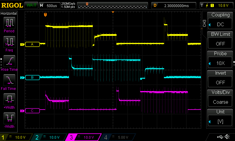
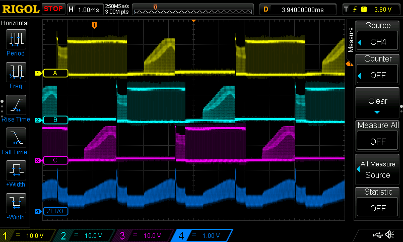
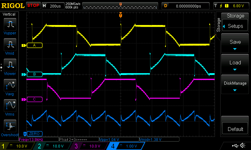
Note: For the next two figures the legend for the different signals/waves is:
Wave 1 (yellow) - Phase A output voltage
Wave 2 (cyan) - Periodic interrupt output (toggles on execution)
Wave 3 (purple) - Comutation interrupt output (toggles on execution)
Wave 4 (blue) - Analog comparator output
As one can see in the figure above, the period measurement interrupt is working fine, however it is the commutation interrupt that is misbehaving. It appears that on the downward slopes the analog comparator detects the transient and this triggers it to count down to commutation. The debouncing on the period measurements prevents this issue for it.
To deal with this issue I used a roundabout method. Given the nature of the single shot (delayed interrupt) used for commutation I was unable to implement debouncing or some other check before the timer starts counting to triggering an interrupt. Instead what I did was that I have the period measuring interrupt reset the counter for the commutation when run (in addition to setting the end mark for the counter). In addition to this, I have the commutation interrupt set its limit to the max at the end of itself so that should it be accidentally triggered, the period measuring interrupt has the most time it can have to set the commutation countdown to run properly if triggered early due to transients.
The results of these minor tweaks (only two lines of code!) had immediate results. Even with PWM modulation the system worked much better.
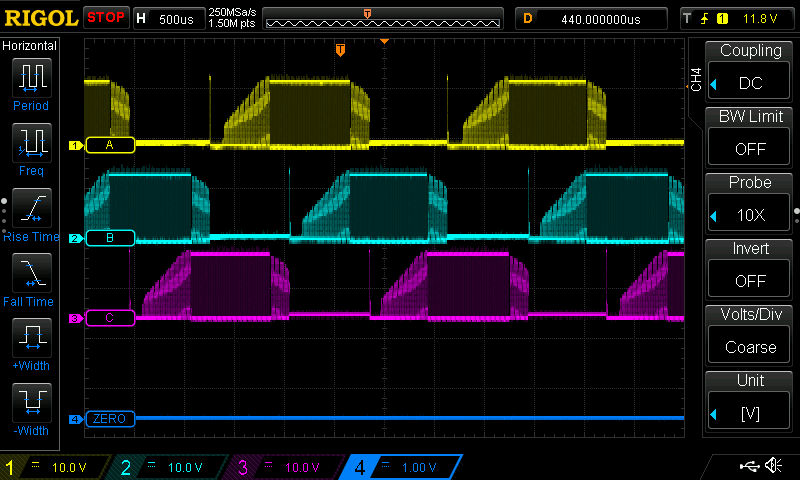
At full power one can basically see the voltage on phase A resemble a textbook example of an ideal BLDC voltage waveform! In it the aforementioned transients are pretty clear to see as well.
Motor Success
At this point I could confidently say I had the foundation of a successful BLDC BEMF ESC! Granted my operating speeds were between ~30% and 100% PWM duty, this could probably be extended with better filtering in the BEMF stages.
I recorded a video of the test motor in action! On the oscilloscope the waves match the legend below.
Wave 1 (yellow) - Phase A output voltage
Wave 2 (cyan) - Periodic interrupt output (toggles on execution)
Wave 3 (purple) - Comutation interrupt output (toggles on execution)
Wave 4 (blue) - Analog comparator output
Unfortunately I did not record a video of it with a decreased duty cycle, but it worked within the range stated above.
Verifying Communication Features
Thanks to using the Arduino framework, communications are heavily abstracted for me and my code, so there has been little to change since the earliest version from V2. However I had yet to develop a PWM input system (the conventional input for drones) and also needed to update the digital systems to allow the LED to be controlled.
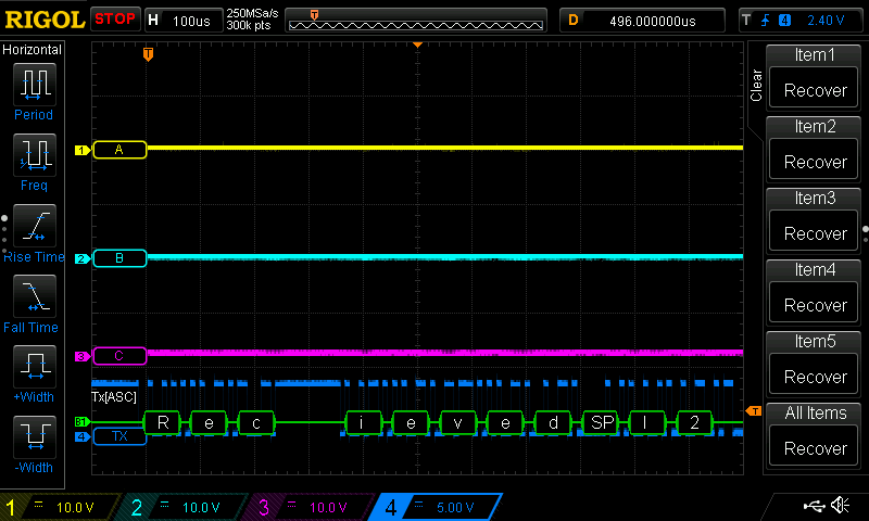
UART
Thanks to the Arduino library this hasn’t had a reason to change much since V2, I only had to add another command option for blinking the LED. I also refactored the command switch with a chain of if {...} else if {...} so that it would be safer and avoid accidental drop through if I change it again in the future and forget a break;.
A nice thing I had only realized when I started working with the UART was that I could use the UART decoding feature of my oscilloscope to print messages on the screen with a single connection!
I2C
This transitioned from a switch structure, to the slightly less visually pleasant but safer if {...} else if {...} chain just like with UART, as well as adding a blinking command.
In testing, I found that blinking and didn’t work and would freeze the ESC, while buzzing would start but fail to stop while also freezing the ESC. I realized quickly that this was due to them relying on millis() and delay() which do not work within interrupts. This is unique to I2C receive/request events since they are triggered as interrupts, whereas I poll the UART for serial commands as part of the main loop.
For this reason I prepared non-blocking function for these features that would record a desired blinking or buzzing to then be enacted by another function once returned to the main program loop. These functions were then also used in the UART communication function. For buzzing the functions are setToBuzz() in interrupts which is then enacted by runInterruptBuzz() in the main loop, for blinking these are setNonBlockingBlink() and nonBlockingLEDBlink() respectively.
PWM Input
For PWM input I had originally envisioned using one of the timer type B’s in the width capture mode. However since both were being used for commutation, I has to go about doing it with more traditional pin interrupts on both edges. On a rising edge it would record the start of pulse, and then on the falling edge it would determine the microseconds since the start.
This seems to work so far, although I should add some debouncing in software just in case. I did however add a time out system to allow the ESC to check it was receiving regular input if it was depending on PWM input.
Proper Motor Tests
Throughout the development process for all my ESCs thus far I had used a small motor salvaged from an old CD drive that I soldered leads to. This was useful for testing for a few reasons: cheap, easy to source a replacement, compact, slower, and [relatively] high winding resistance of about 2.5 Ω (so the stall current would be manageable if my code failed).
My drone however was going to use proper motors. These were going to draw significantly more power and lead to more extreme operating conditions as a result, notably with more intense transient effects. So I needed to test the ESCs with these to verify they were flight ready.
The motors I have are EMAX’s ECO2207-1900KV model. These are rated for 1900KV which roughly means they will rotate about 1900 RPM for each volt they are driven. This means that at the roughly 12 V I am working with they are expected to rotate at about 22800 RPM (380 Hz, commutated at a rate of 4560 Hz (12 steps per rotation), or once every ~220 us) at full power! In addition to this massive speed, the winding resistance was only about 70 mΩ so the stall currents would exceed 100 A at 12 V.
With nothing else to really develop implement on the ESC (at least given the hardware available) I soldered the normal motor in place of my test motor and got cracking on these power tests, hoping for the best.
My plan for the power tests was similar to the tests I did to develop the code:
- Buzzing
- Spin up
- Spinning at full power
- Spinning at a lower power level using PWM
Motor Issues
This jump in power draw quickly led to issues, for both hardware and software to contend with.
The most immediately visible one was the significantly increased power draw causing brownouts of the system when buzzing. These brown-outs caused me to lose two ATtiny1617s, probably due to their supply voltage dropping below the voltage on some of their pins (due to capacitors, likely in the BEMF feedback network).
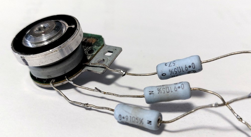
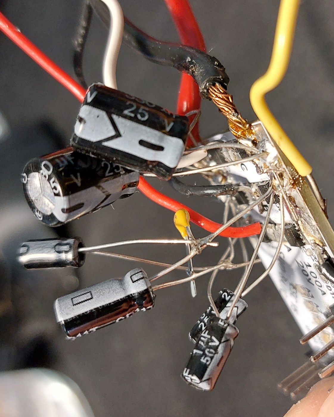
I soldered on some more capacitors to the supply rails, raising the capacitance to 660 uF as I saw in other reference designs for ESCs. However given the non-ideal sourcing of my capacitors and their long leads, I’m fairly certain that the non-idealities are piling on, inhibiting proper filtering. To counter this I tried adding more capacitors of different values to try and cover a wider range of frequencies better.
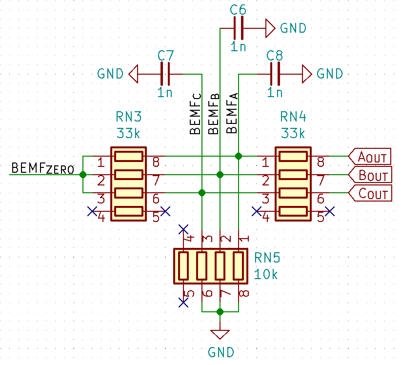
In addition to the capacitors on the power supply, I increased the factor of division used in the BEMF feedback network. I changed RN4 from 33 kΩ to 56.2 kΩ, changing the division of phase voltage fed into the comparator from a factor of 4.3 to 6.62. This will reduce the effects of voltage spike on motor phases so that the phases can reach up to 33 V without exceeding the 5 V for the ATtiny. This protection does mean that in general the BEMF feedback signals will be harder to distinguish.
Power Buzzing
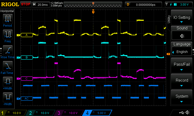
With these hardware changes in place, it was time to attempt some software solutions, as well as more thorough monitoring of the system. Beginning again with the buzzing code I probed a few points of interest (listed below). The buzzing continued to cause brown-outs, but was no longer damaging the ATtiny.
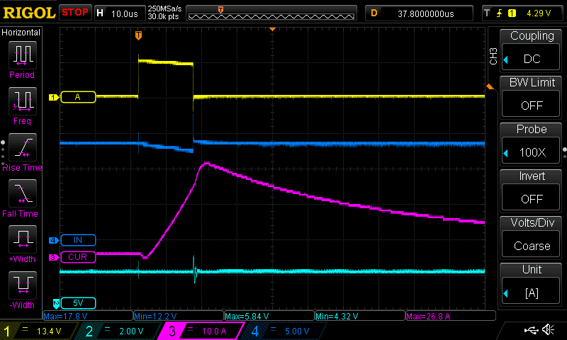
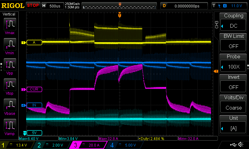
In the next few figures the waves correspond to the following signals:
Wave 1 (yellow) - Phase A output voltage
Wave 2 (cyan) - 5V supply line
Wave 3 (purple) - Current draw (either through phase A or entire system)
Wave 4 (blue) - Main supply voltage (nominally 12 V or 13.2 V)
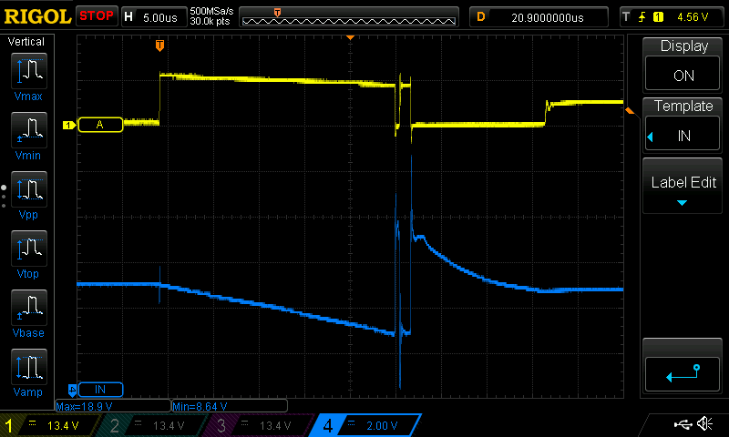
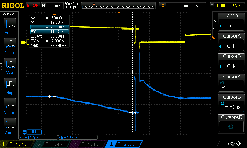
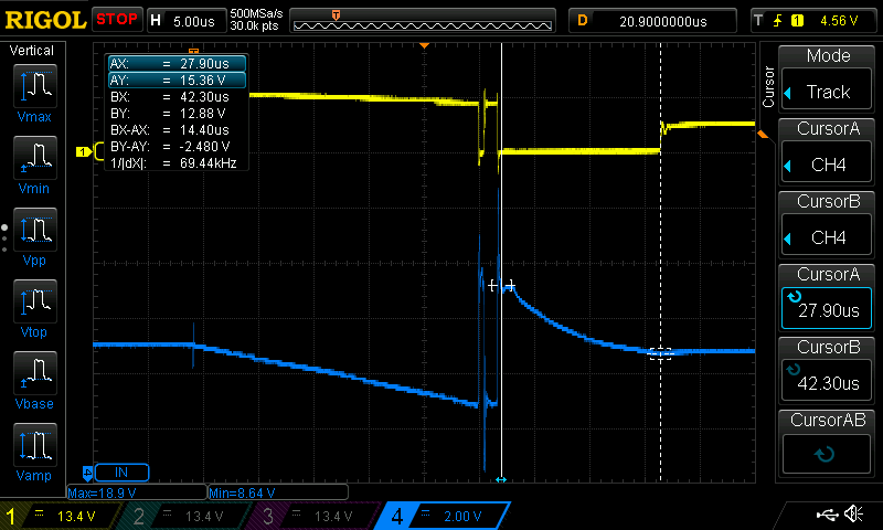
Looking at this we can see that the supply voltage linearly decreases with time once the buzz is started, down to about 11 V which is roughly about when the under-voltage lockout is triggered on the MOSFET driver chip, disabling itself. This first slope takes about 25 us, followed by a sudden rise in voltage on the supply as the current is cut to the phase for a fraction of microsecond, before the phase is re-enabled for a bit under 2 us until the MOSFET driver seems to shut off prematurely again. A normal buzz energization period is 50 us, this is only roughly 30 us until the system restarts.
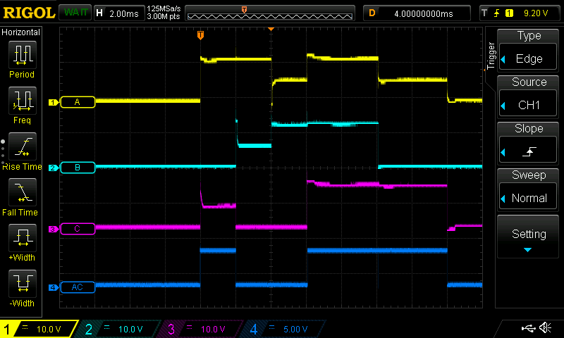
To try and get a better idea of what was going on, I added a probe on the 5 V supply for the ATtiny to see if it was victim to some noise, and then a current probe for the current going into phase A.
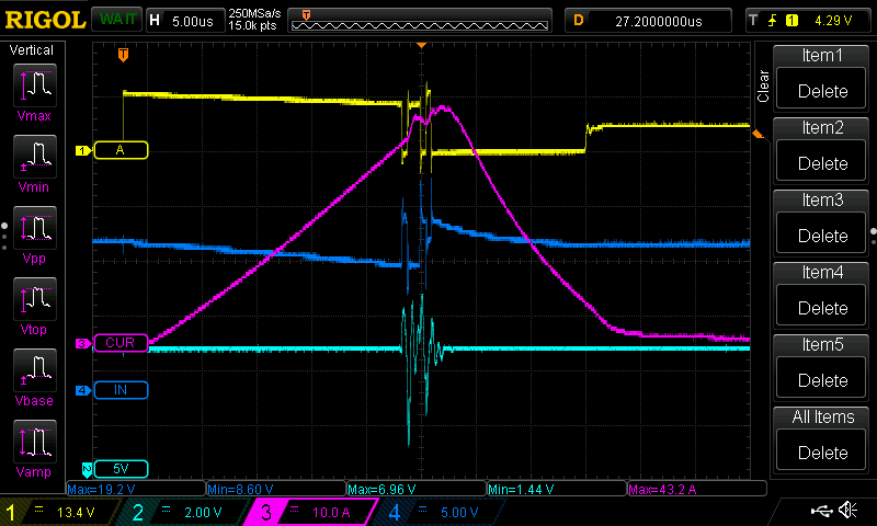
In this it is clear that the current draw is immense, reaching over 40 A before the brown-out occurs. I don’t have a comparison to make to my testing motor, but this is probably an order of magnitude higher of an inrush current.
My solution to get buzzing working was a little less elegant than what I probably need, but it worked. I just reduced the duration the phase was held high only 15 us! This avoided drawing enough power to cause brown-outs, and since this motor is more powerful than the test one, even with this reduced period the buzzing is louder than before! There is also less noise around switching due to the reduced energy levels, with the peak current being under 30 A.
Power Spin Up
With my experience getting buzzing to work, I know that I would need to reconsider my approach to how I spun up the motor. A 30 us pulse at full power was enough to brown-out the system, there was no way I was going to be able to hold a phase fully energized for several milliseconds like I did for spin up.
This necessitated that I develop an improved software soft-start for the motor. My initial approach was to start at a low duty like 15%, and then gradually increase it alongside the stepping frequency as it spun up to some end level like 50%. My initial attempts were moderately successful at getting the motor to start spinning, however they were marred by brown-outs whenever the motor got to step intervals of about 750 us regardless of how gradual or sudden the spin up was to that point.
Further testing shows that 20% PWM seems to be the upper limit of stability for the system in spin up, otherwise the current draws start to exceed 40 A which is the limit of the power supply I am using.
At this point I feel that both my hardware and software are at their limits. I likely need to implement another feedback mechanism other than BEMF to improve the spin up. This will likely take the form of a shunt resistor.
Potential Solutions
From my testing I have noted a few things I could try to address the issues.
- Adding surface mount ceramic capacitors for bypass/decoupling/filtering motor transients
- Try using PWM on the low sides (instead of just holding them low)
- Try using the CCL (“Configurable Custom Logic”) on the ATtiny chip to combine the comparator and PWM state for zero-crossing logic
- Look into implementing a closed-loop wind up system for motors. Likely will need current shunts to be added.
- Application Note 1914 (AN1914) from Freescale Semiconductor has some suggestions
Overall this potential solutions largely steer me to making a new board revision. I will look to also improve the layout of the board for usability reasons.
Outcomes
I have what I believe to be the foundation of a proper, working ESC’s firmware and hardware design. I feel that I will soon reach the end of this project with one more revision to address my main issues:
- Hardware revision to reduce the prevalence of transients, and to better handle them when they arise.
- Improve the spin-up routine to better handle high power motors. Likely with some basic current monitoring.
It’s a shame I lost my initial test motor, but I will not let its loss be in vain!