ESC V3
Table of Contents
Overview
A minor revision of V2, primarily to try preventing the issues I had with multiple voltage rails repeating. I did not change anything related to the microcontroller so I could theoretically use the same code from V2 and drop it into V3, and vice versa. Yes, that means my PWM issues would still be present on this one.
In addition to these power related changes, I added two status LEDs. One to light up when there is power applied to the board and another to be controlled by the microcontroller.
I ordered the boards but never bothered to assemble them, as I was already planning V4 so I didn’t order parts for what amounted to an obsolete version.
Detailed Report
This revision was mainly a pruning of some thorns in V2 related to development: mixed voltages and expressing status to the user. You can read into what went into designing V2 on its page, here I will focus only on my changes:
- The removal of the 5 V regulator.
- It is now dependant on an external 5 V supply for the microcontroller.
- This was done to avoid issues related to unequal 5 V through the system and with programmers.
- The addition of Schottky diodes to supply line for the MOSFET driver.
- This was done to ensure that the driver chip would always be supplied the higher of 5V or Vbatt
- The addition of two status LEDs.
- One controlled by the microcontroller (user)
- One to illuminate when power is applied to the system on Vbatt
- Proper programming connections for SPI ISP
Circuit Design
Since this is the basically the same as V2 (and thus V1), please refer to V1’s section on the circuit’s main design. My changes to the design were:
- The removal of the 5 V regulator subsystem
- The addition of Schottky diodes to supply line for the MOSFET driver. D6 and D7.
- The addition of two status LEDs. D4 for the microcontroller and D5 for power indication.
- The rearrangement of how the RESET signal for the microcontroller is routed for programming.

Layout
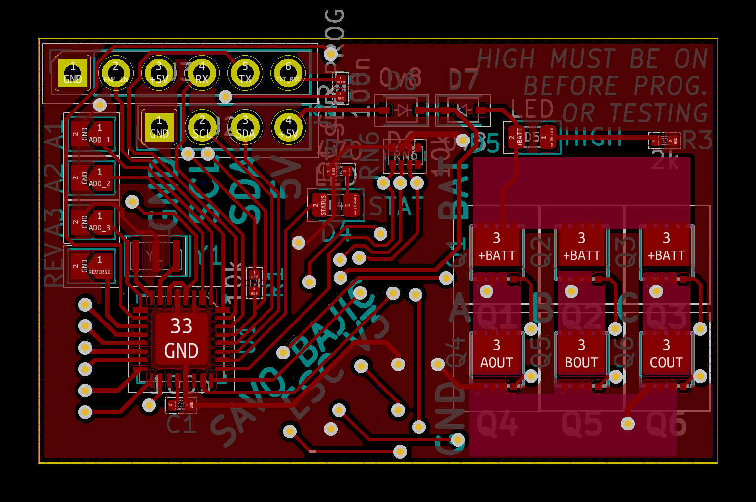
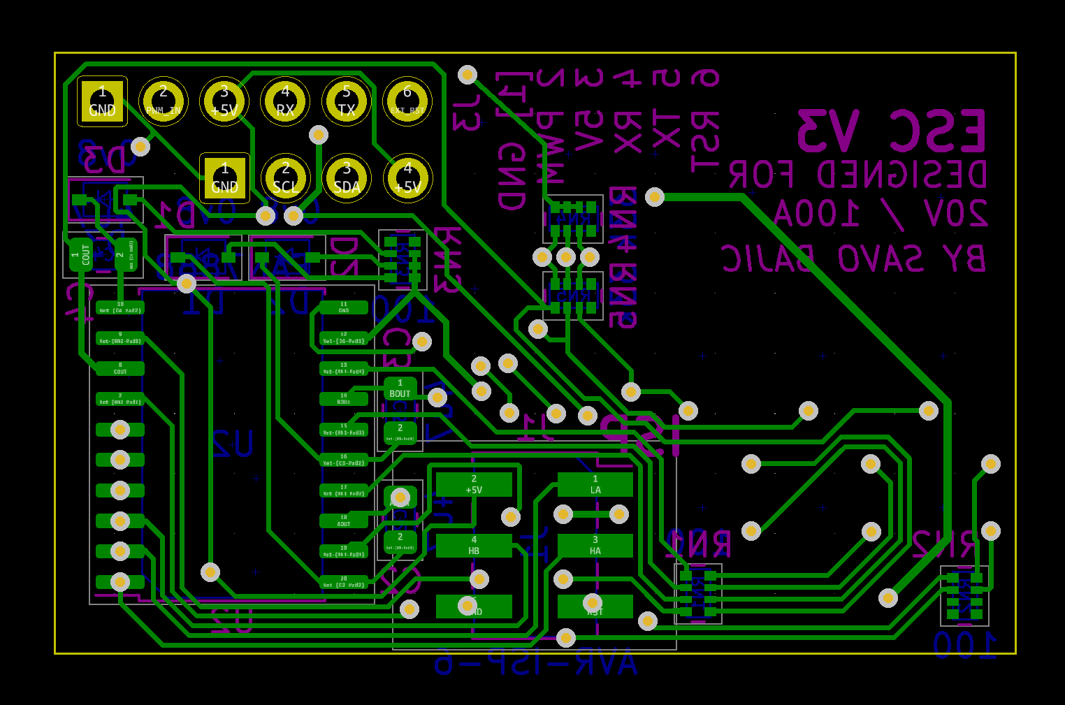
I started by reusing the layout from V2, so I will link to its layout description for details regarding what went into that layout. Below you can see the overall revised board for V3.
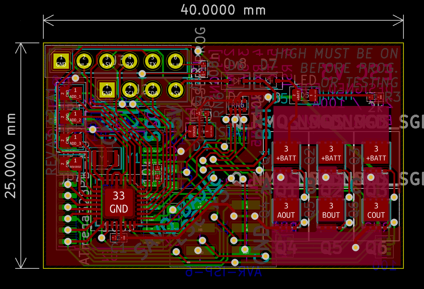
All changes that occurred were on the top side. The complete removal of the 5 V regulator was in the top right. Three of the four new diodes sit in the space it formerly occupied, the only exception being the controlled diode (D4) sitting in the centre of the board.
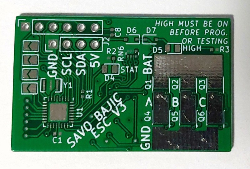
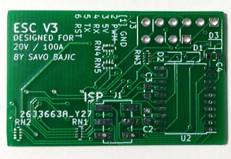
The bottom of the board remains largely unchanged from V2, other than changing the silkscreen text to reflect the version number and the redone trace for RESET from the SPI ISP header.
Assembly
None of these were assembled. A revised stencil for it wasn’t even ordered, I simply planned to wipe off the excess solder not needed for the regulator and hand solder the new components if I were to assemble it. Here are some pictures of the PCBs I got anyways.