Vehicle Control Unit (VCU)
Table of Contents
Overview
The biggest project I undertook while working at Engineering Design Lab was leading the design of their in-house Vehicle Control Unit, VCU - at least the electrical portion! Based on an initial scope I established with Tomek (the founder) that was revised a bit over time, I set off and made a general purpose small vehicle controller for use in novel small electric vehicles.
This project covered the entire duration of my two year involvement with EDL, as a contractor and then as a full timer - as a result this is definitely the project that I have fleshed out the most in my electrical career thus far and learned the most from.
Objectives
The initial scope was set by Tomek and his experience in working on micromobility products, where he found that the electronics were often the major challenge to getting a project going. People were unfamiliar with designing electronics generally and didn’t know where to start, struggled to make them survive field operation, or they under engineered their systems and needed to extend them to name a few issues.
Our discussion led to the following objectives for the VCU:
- Stand-alone unit (not dependent on multiple parts)
- Enclosed in an IP67 enclosure with matching connectors
- Compact enough to fit easily on a vehicle like a bike
- Have IoT connectivity so people can connect smartphone applications to their vehicles
- Support common electrical interfaces one would need
- Allow for people to mix vendors and not be constrained to a specific ecosystem of parts
That last point evolved into one of our major selling points.
Takeaways
As I left EDL and this project, I can say that a few things stuck out to me regarding product development, as well as adapting to industry generally since this was my first technical job that was client-facing.
- PCBA services really save you headaches and worth the money for confident prototyping
- Marketing a product is hard, especially to start-ups
- The support you have for a device is almost more important than the device itself
- Don’t be shy to iterate prototypes, far better than revising larger production runs
- You need to think holistically on what you are trying to accomplish with a product, not just maxing out some performance benchmarks
Design
On paper it was a simple device to help novel electric vehicles come to market faster since in EDL’s experience it was always the electronics that were a big unknown and bottleneck for clients developing novel electric mobility products.
Once we established the scope, I was entrusted with essentially all the electrical design from that point on of the VCU. I drafted the original feature set with a bit of feedback with some collaborators of EDL at the start of 2024, and it remained constant barring some minor tweaks between revisions, and it advertized in the promotional material. In summary it brought the following features:
- Working power input voltage range from 12 V to 95 V, with a limited number of inputs and outputs operating at this level
- WiFi and Bluetooth Low Energy connectivity
- Two independent CAN communication buses
- Low-voltage general purpose input/output pins configured for either 5 V or 12 V operation, some of which offered analog readings
- Basic user interface through an RGB status LED and button
- Internal peripherals like an IMU, flash, and an expansion header for expansion boards
Circuit Design
The first thing I had to choose was what microcontroller, or at least family, I would use for this product. Given the need for IoT connectivity I looked for a family with that integrated as well as a robust developer support system. I found that Espressif’s ESP32 chips met our needs, initially I started with a basic ESP32, before shifting to the ESP32-S3 which greatly simplified development with its USB interface.
Once that was selected I went forward finding ICs to achieve all the features we wanted such as a second CAN bus (ESP32/ESP32-S3s only have one internal CAN bus peripheral). In addition to choosing ICs based on their operational behaviour, I also selected parts based on if they offered smaller packages - ideally leadless - since I knew that space would eventually be at a premium. Most of the parts I selected at the start remained until at least when I left.
PCB Layout
The most challenging part of the electrical design was certainly the layout. The first version was a two layer PCB but quite large, once we worked to shrink down the size we went multi-layer and that’s where I began to draw on my graduate experience of laying out some ICs to lean on some tricks to get the job done. One major method I used was using different layers for North-South or East-West routing, leaving the heavier outermost layers for power routing.
One design feature that I did to enable the thermal performance to be improved in the future was that I put all the high power components on the bottom of the PCB. This way they could be easily interfaced with thermal pads to the enclosure’s metal base plate so it would act as a heat sink for them. The ESP32 was put on the top to better propagate its radio communications, then the rest of the supporting circuitry was sprinkled around the board. The ESP32’s fully reconfigurable GPIO system meant that I could reassign pins to simplify routing for myself not being stuck to certain pins providing the functions we needed.
Across the revisions it was the routing that really changed the most for electrical design. One story that sticks it out is how I despised it when it was decided to add more mounting holes to the PCB. Initially we had a hole in each corner but later it was decided to add three more to fasten down potential expansion boards to better survive vibration - luckily I was able to place them in areas that didn’t need that much rework but it still felt like a bit of surgery when I had to clear the traces that previously routed so nice in those spots.
Enclosure
I mostly stuck to my lane and focused on electrical work, however I did help guide some of the design of the enclosure. Most of it was through the lens of electrical work, so indirectly influencing the design via connector choice, while other times accommodating mechanical requests like adding mounting holes. Since EDL historically focused on mechanical engineering this portion had much more team discussion around it.

Connectors
It was the primary connector that was among the most fiercely debated design choices we made for the VCU, and really held up our initial revisions. Some feedback from our collaborators even initially directed us to consider multiple connectors to split low and high power signals!
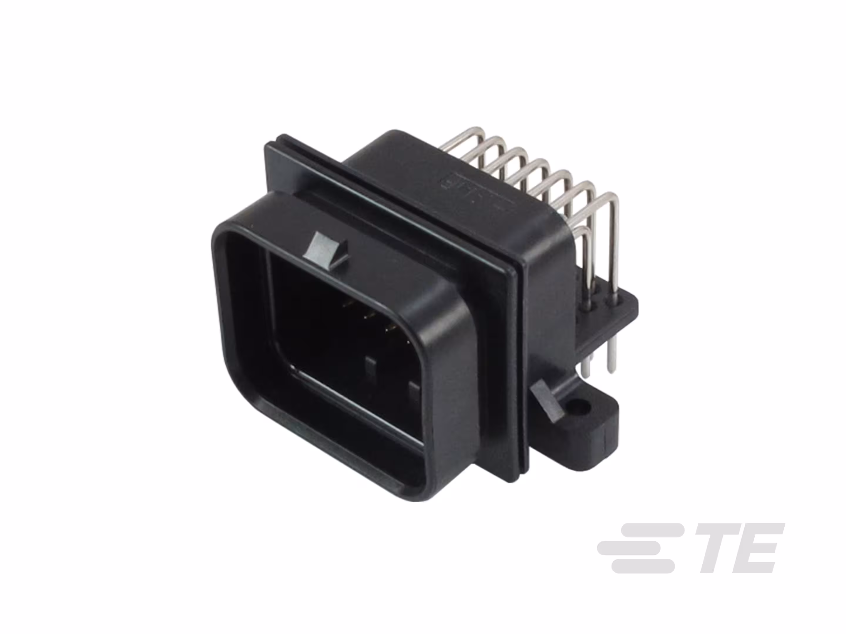
We knew from the start that some sort of panel connector would be needed to make the connection through the enclosure, and the original approach by EDL was to try and find a connector that was sealed with O-rings due to their proven long term reliability and commercial availability compared to a custom gasket or enclosure to mate with the connector. However the connectors that were tested were unsatisfactory from an assembly simplicity standpoint. In my view particularly they ill-suited because they were unable to connect directly to the PCB since we had to use an intermediate harness or ribbon cable which contributed bulk that would need to be accommodated inside the enclosure. After some discussion we settled on a single 34-pin TE SUPERSEAL 1.0 connector - which was my suggestion at the start of the project.
In later revisions when a USB-C connection was introduced, it was much less of a debate in the team since it did not influence the enclosure significantly. I simply found an IP rated USB-C connector and passed the mechanical design recommendations to my colleague it incorporate into the enclosure.
Housing
At the start EDL pushed for me to find a commercially available enclosure that we could use for the VCU, making sure that it met the requirement for ingress protection without depending on the potting. After trying a couple options this was quickly abandoned in favour of designing a custom enclosure from the ground up. The reasons were mainly that there weren’t many options to begin with that met our criteria, and those that did were far too oversized. They were also all just kind of ugly.
So we got a blank slate to work with for our custom enclosure other than that we had to fit the connector - this was when I started the second version of the PCB so I proposed an estimated PCB outline for them to fit and we went from there.
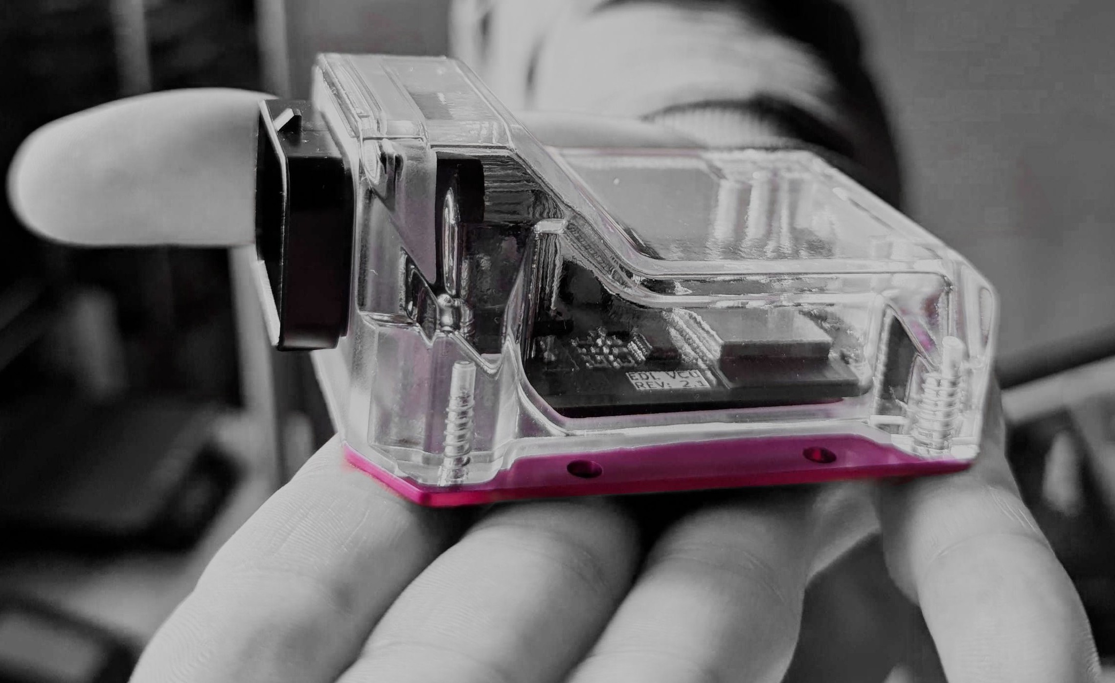
We decided to try and make this as simple as we could, ideally a two part enclosure that would clamp together around the PCB. EDL was committed to making the VCU IP rated without depending on potting so that it could be serviced in the field and dissembled for sorting at end of life disposal. To that end, the sealing was achieved through a custom rubber gasket that would sit between these two and go around the connector on the PCB such that everything could be squished together to seal. The result of this was a clear plastic cover that be screwed to a metal base plate/lid.
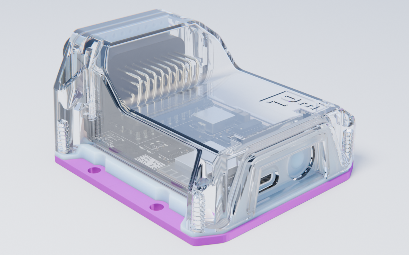
The overall shape and design remained constant from the first version. Later revisions of the enclosure accommodated a way to press the user button as well as plug in a USB port by adding a second plastic piece to retain the gasket around these features on the face opposite the main connector as highlighted in the picture above.
Iterations
Over the two years I worked on this, there were many revisions. I gained an appreciation for the iterative process and learned how it is done in industry compared to when working on an academic or personal project. Hint: you’ve got money now! Careful though, your time is much more important! I’d like to highlight some of the major milestones.
Electrical Revisions
When I left we were on our seventh (7!) revision, however not all of them represented equal advancements in the development as I followed an arguably strict revision system where any electrical change such that two produced boards would not be electrically identical was a complete revision, I used sub revisions, e.g. 5.1, only for when I adjusted design files between rounds of production reviews and quotes to avoid confusion when referring to them.
Board Revision 1.0
Ah the first version. This one was designed for one of the oversized commercial enclosures that we initially considered, so I had enough room to put everything down on a single side and with only two layers of copper. This single sided assembly was advantageous in that it made it much easier to probe the inner workings of the board without needing to flip it all the time. Electrically this proved the circuit designs I made were valid and we were able to meet all the goals.
The production of this one was a learning experience for me though. I had ordered the PCBA through JLCPCB using their service, which although it was fast and good, they didn’t have all the parts we wanted in their inventory so I elected to have us complete the installation of the few parts they wouldn’t be able to in the interest of time. Looking back this was clearly going to complicate things since we wouldn’t be able to use a stencil and we’d be actively working around already soldered components. In the end this led to an abysmal yield of only a single board of the five ordered working entirely corrected, two more partially operable and two were completely toast. From this experience we committed to having our PCBAs done entirely by our contract manufacturers.
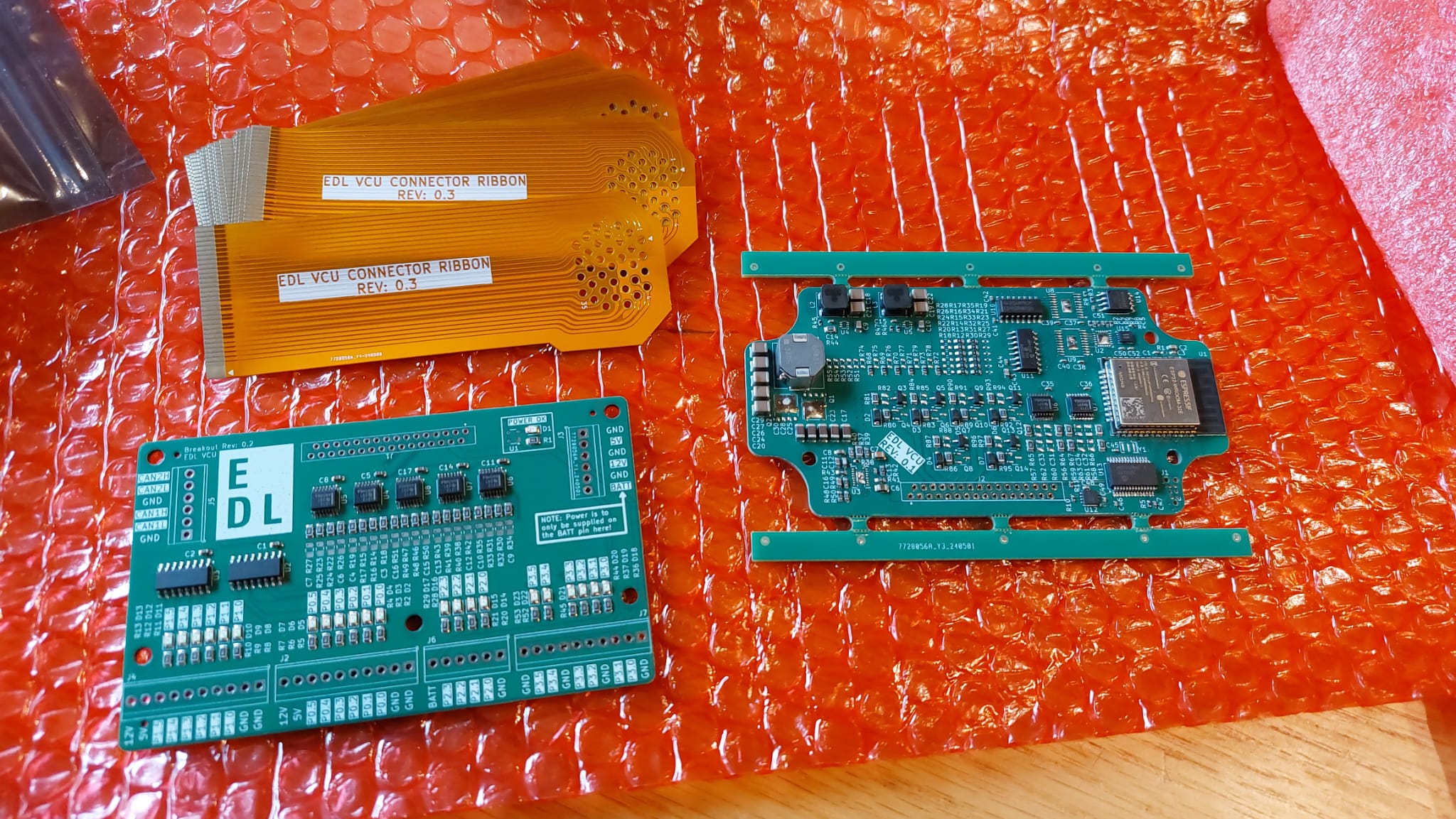
Note: I labelled these boards as Rev 0.1 since I wanted it to be clear it was a prototype to my colleagues.
On the left in the picture above is a little breakout board I did that could connect in place of the connector to simplify development for our both our end users and us. Once we moved from the ribbon connector in the next version we never updated it for the new connector.
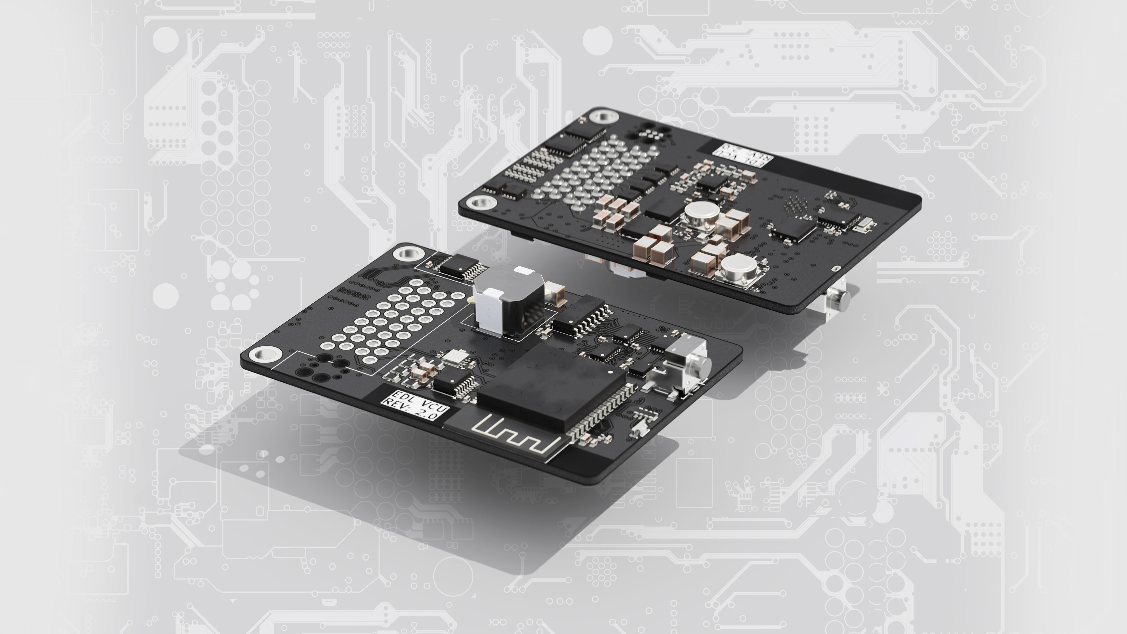
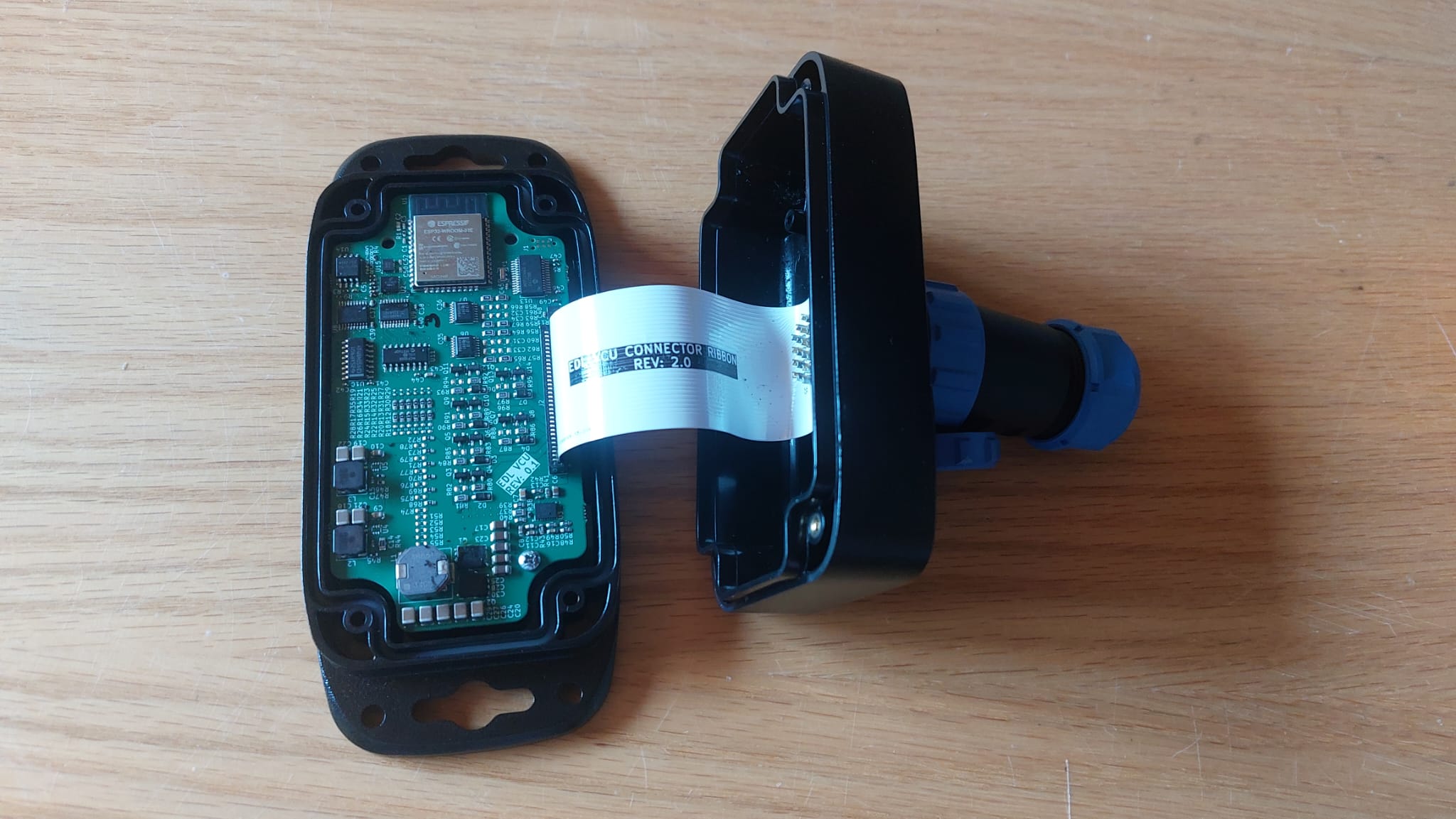
Board Revision 2.0
This was the version that really set the form of what the VCU would be, it was designed to fit inside our custom enclosure. It was largely the same electrically, with only a couple minor tweaks to the high power GPIO. As such, most of the effort was in the routing of the board. We upped the layer count to six, four for routing with two ground planes, and made use of double sided assembly to fit everything into the enclosure.
Board Revision 3.0
This one changed the electronics a bit: we switched to the ESP32-S3, added the header for expansion boards, and added circuitry to allow for the VCU to be entirely software configured. Earlier versions used solder jumpers to configure some of the ports to work at 5 V or 12 V, which meant that we would need to adjust our production runs based on client specifications making stockpiling impossible, and also it would prevent users from easily changing their systems in the future.
Board Revisions 4.0 to 6.0
These were all primarily slight nudges mechanically, adding mounting holes, adjusting some part placements, etc. There were some minor electrical changes such as simplifying the multiplexing circuitry for low power GPIO but much of it was transparent to our end users.
Board Revision 7.0
My final, yet smallest incremental change. I am singling it out since I had to do it for one not-so-little screw up, where my solution was to just add two solder pads - nothing else changed from 6.0, nothing.
The screw up I addressed was there from the version 1.0 going through all our designs up to this point; I had CAN terminations for both buses on every VCU. This isn’t necessarily bad, but it meant that we were unable to have more than two VCUs share a CAN bus lest it over terminate the bus and cause it to fail. The inability to have several unit share a CAN bus went against one of our proposed use cases. So I had to make the minuscule change of adding solder bridges to the VCU PCB to enable or disable these bridges as desired in the field. I went through having these present on both the top or bottom so our users could easily access a set of them to enable them regardless of how they were installed.
Enclosure Revisions
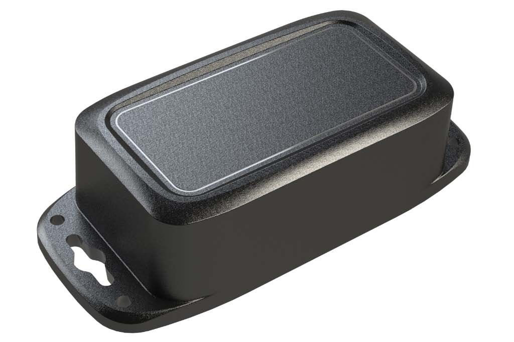
The enclosure underwent several revisions too, although they were generally less extreme - at least from my view. Granted I wasn’t directly involved for the most part. The revisions are also a bit harder to track since different parts underwent revisions at different times so there weren’t such clear distinctions for a snapshot of what a given “revision” was other than the first one being a commercial one, and those that followed were custom.
As you can see this initial version of the VCU’s form was far from something worth selling. The size alone was an issue, without even considering the mated connector sticking out like a spike which would make this that much more difficult to install. Once that was made clear, we embarked on a custom enclosure with a smaller connector system.
Sealing
I know substantial effort went into developing a waterproof seal, which resulted in many iterations of the gasket. Much of the effort was in getting a good seal around the main connector since it was designed to be used for more conventional IP protection where the system is potted rather than gasket sealed. My colleague had to make a gasket that went around the lip of the connector to form a seal, but such sharp corners are notoriously difficult to make a seal for, so many geometries and materials were tested before a suitable design was reached.
Initially to simplify assembly the gasket was actually going to come in two parts: one planar gasket between the base plate and the top cover and bottom side of the connector, with a second small piece to go around between the other sides of the connector and the plastic top. This design avoided needing the gasket to be pulled over the connector like a sweater. However there was regular ingress where the two gaskets met, so in the end this idea was scrapped for a single gasket for everything, that after some tuning achieved the sealing EDL wanted.
Documentation
This was something I learned the importance of as we started engaging more and more clients. When we didn’t have it I found myself regularly answering the same questions from different parties so it became clear that if I went ahead and actually wrote these things out it’ll be better for everyone involved.
Documentation of the system feel into two main categories: the technical papers, and the example code. Both of these were championed by me, with help from some of our roster of interns and some of my colleagues regarding the mechanical aspects. The technical papers were generally reviewed by everyone at EDL to make sure that they could be understood by a technical audience, even if they weren’t electrical engineers.
Technical Papers
These were basically any written documentation related to the VCU that could be printed. In my time I prepared five documents for the VCU system, going roughly from least to most technical they were:
- Promotional flyer. This outlined what the VCU could do and included forms for prospective clients to check off what they were interested in to send back to us for review.
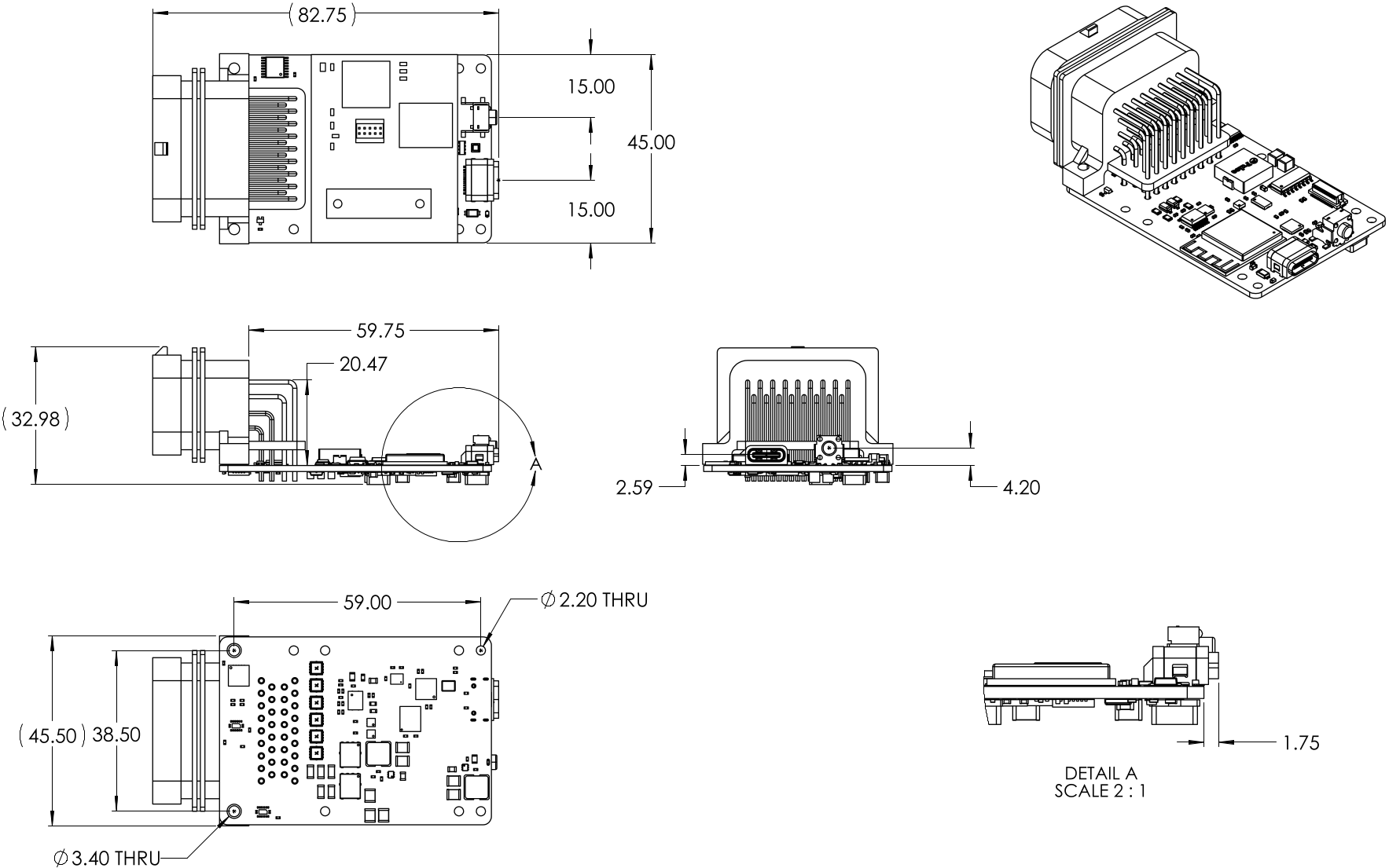
- **Specification / data sheet. This summarized the VCU at a high level, listing electrical features as well as sharing mechanical drawing for customer reference.
- Quick start guide. A short primer on how to get started integrating the VCU into a system and uploading code to it.
- Application guide. This was the bulkiest document by far as it touched on all the parts of the VCU and how clients could make the most out of certain features from a hardware standpoint such as which pins to use for high power - it intentionally avoided mentioning coding much.
- Coding guide. This document was didcated to assisting clients in using the EDL provided libraries in their projects. This was eventually abandoned for reasons explained later.
Of these, the first three were made freely available to anyone through EDL’s dedicated web page for the VCU, while the latter two were provided to committed clients.
Although we initially tried to make a programming guide, we decided to abandon it as we found it wasn’t useful for our clients and thus a waste of our time. Speaking with our clients, consulting with EDL’s collaborators, and reflecting on our own experiences, we decided to instead invest in documenting the code in situ with well formatted comments through all our header files. This way the explanations would be right where a programmer would first look for it: in the source code, rather than needing to refer to a separate document. We then used the remaining energy we spared from the programming document to expand our library of example code and make them better for those that would use them.
Making these documents took a fair bit of time, especially when I was revising them to balance technical discussion and not swamping the reader with data - an issue I have when I write these project pages for my website. Initially they were done using standard word processing software, but I migrated to LaTeX to achieve a better consistency across their formatting as well as implementing proper version control of the texts.
Over time as we marched through revisions of the VCU these would be updated. We would try our best to cover all VCU revisions, but every so often we would have to drop our support for certain ones in the documentation to keep them simple to read.
Example Code
I never realized how much work it takes to make useful sample code, probably explains why so many projects you find online lack many.
When you’re making what’s essentially a development kit it’s critical to have some examples so people can get a handle on how your system works, and the VCU was no different. Luckily we had to really write the baseline examples/demonstrations to test out all our hardware features during development anyways so all we had to really do to elevate these to an example for our future clients was just polishing them up with nicer comments and readme.mds.
I wrote most of the example code, however I did delegate some onto our interns which I then reviewed before we released them to clients. Since we were using ESP32s, we also had their examples we could lean on and rehash quickly as needed. Most of our more complicated examples arose in response to our clients requesting certain features (namely CAN) be demonstrated more, and then we would reuse them for other clients once we sanitized them of anything to identify each other.
When I left we had examples for demonstrating all the basics specific to our VCU hardware, about 20 examples in total.
Sales and Support
Of all the aspects of the project, this was by far the most foreign to me going in. I generally solved a problem people explicitly came to me for help with, so there was no need to convince them they needed the circuitry I was offering. Fortunately Tomek handled most of this, although I was given some primers on what to say and what to avoid in conversations in clients once they showed some interest in the VCU. Eventually as we went to some trade shows I was entrusted to pitch the VCU to prospective clients on my own!
One memorable pitch I made was when we went to the Consumer Electronics Show, CES, in January 2025. I was manning our little booth and a group of engineers approached as opposed to the usual company representatives and they were interested in our little controller. After some chatting they seemed interested to employ them in their testing, which naturally led to me asking them what exactly they were testing.
They giggled a bit and told me simply “missiles”, and then handed me their business cards which were for a prominent Military supplier, with titles to the effect of “Launch System Engineer”
When it came to supporting the product I was more comfortable from the start since this was me talking engineer to engineer. This support would usually start with just passing them the documentation packs we had, and then lead to calls if they had further questions. Supporting our clients really helped inform our efforts in developing the VCU since it helped us locate areas that were not properly covered with documentation or examples. For example, our first VCU client was instrumental in really helping push us in developing and testing our CAN related work to the great level we had. As time passed and our documentation improved our direct support through calls and emails really dropped as clients found all they needed in writing.
Reflections
Needless to say I am proud with my efforts, especially on the technical side. I feel that I made what was needed for our clients and something that should help accelerate peoples’ product launches and is probably as easy to integrate as we could make it.
Along the way I learned a significant amount about what it takes to not just design a product that someone else will use, but what it takes to make something they want to use. A lot of this came down to supporting our users with adequate documentation and consultation, not necessarily the technical prowess. A line that sticks out for me is that people want polished products, not necessarily the top technologies.
I hope to draw on this experience for the rest of my career, and maybe eventually try to make something from scratch as my own product.
Best of luck EDL, I hope it works out the way we hoped!