ATtiny1617 Dev Board
Table of Contents
Overview
I wanted to make a little development board to experiment with the ATtiny line of chips after learning about them working on my fourth ESC revision and found them to be quite cool.
It didn’t need to be anything special, I just basically wanted a breakout for the chips that made it easy for me to connect it to a breadboard, supply power over USB, and then program using my ATMEL-ICE.
This was the personal first project I had gotten sponsored! It was from PCBWay, which covered the production of the boards I talk about in assembly.
Circuit Design
The circuit is pretty simple since the ATtiny1617 which I primarily intend to use this board for requires only decoupling capacitors as its minimum supporting circuitry. I accidentally omitted these capacitors on the first revision of the board I made which led to infrequent glitches. Other than those capacitors, the rest of the components served to breakout connections as required by the ATtiny:
- Mini-USB header to supply 5 V power to the board. Using these since I have a few connectors left stock piled.
- Two sets of 2.54 mm pitch headers for all the GPIO and power connections from the ATtiny.
- One IDC 2-by-3 connector for attaching the ATMEL-ICE for programming.

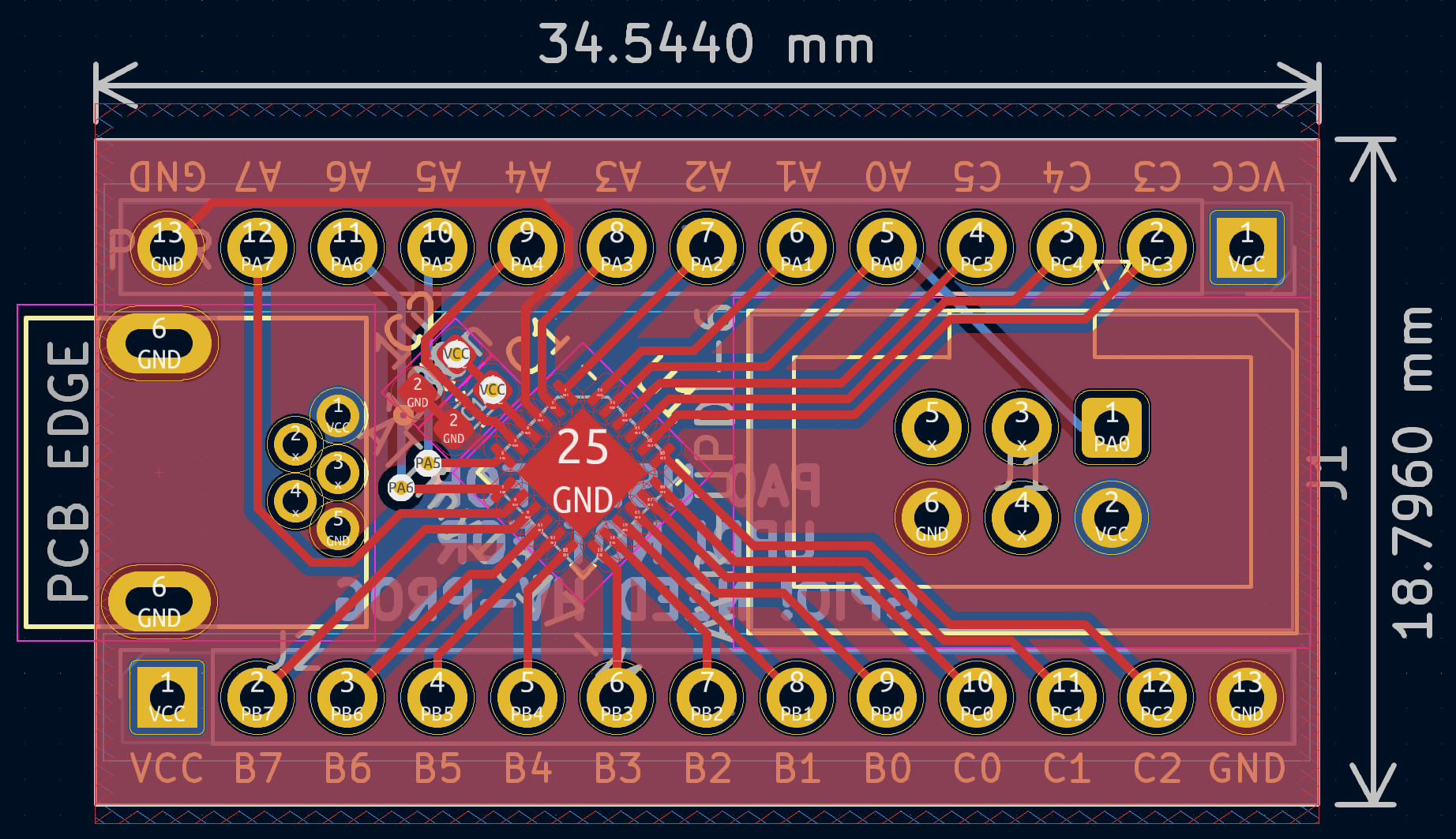
Board Layout
This was simple thanks to the simple circuit and it was almost a single layer board! To facilitate an easier fan out of the GPIO connections of the ATtiny I placed it on a 45° orientation at the centre of the board. The connectors for power and programming were placed at opposite ends, while the GPIO headers ran along the length of the sides with labels for each pin.
Assembly
The boards were sponsored by PCBWay, my first time getting sponsored like this and also trying out their services! Since this was a relatively basic project I opted to hand assemble the breakout boards, without a stencil for the solder paste. So I just asked for the boards to be made. From order to delivery service was good and fast, the boards arrived less than 10 days after I ordered them.
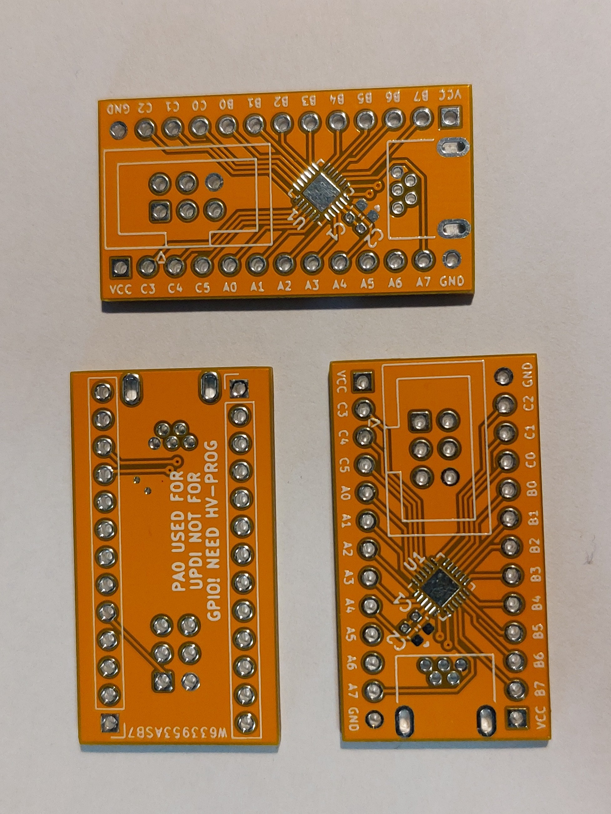
I started with the surface mount parts which needed me to hand dispense the solder paste on the required pads. This was easy to do and with minimal effort I was able to solder all the parts without any shorts thanks to the solder mask. Soldering the through hole headers was a breeze too with the pads wetting easily.
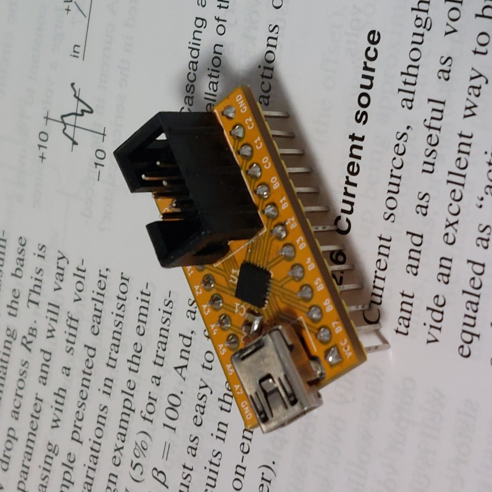
Overall, these are great quality boards and they deliver on my expectations. I look forward to trying out PCBWay for more complicated projects down the line!
Programming and Testing
I connected a USB cable for power and nothing started smoking which was good, a quick check with my multimeter confirmed that the power rails were at the right levels.
With the power verified, I connected my ATMEL-ICE and started programming. I was able to set the fuses for the microcontroller to expect a 5 V supply and operate using its internal 20 MHz oscillator. Afterwards I was able to successfully upload a simple program to toggle GPIO pins.
This test program worked well, the chip was toggling the GPIO pins as expected. So I was confident the boards worked as intended.
Conclusion
The revised board works flawlessly. I’ve already used it to help me develop a project for a client! It was crucial for trying out some of the less often used features such as multiplexing peripherals or outputting the system clock to ensure that the microcontroller could deliver the performance I needed.
One drawback to such a simple development board is that communicating with the chip requires hardware external to the board itself. I feel that given the these chips are not meant to be used in complicated applications that this is an acceptable compromise to make.
The boards from PCBWay came out nice and clean, easy to assembly by hand for both SMD and THT components. I’ll look to use them more in the future.
Future Changes
If I am to make another revision, then I would look to change the USB connector to type C, and add a 3.3 V regulator that can be used as the main system voltage to make it easier to develop 3.3 V systems as they become more common.
A set of built in LEDs might also make it easier to work with this board, but would probably need the board to increase in size to accommodate them properly.