Edit Machine
Table of Contents
Overview
A visiting friend of mine, Bennett, was interested in developing his soldering skills and interested in up-cycling e-waste. He has a habit of setting weekly goals for himself so we decided to make a little circuit to help make finishing each goal a little cooler.
After some lengthy debugging and slight modifications to our original scope the final board was assembled on some perforated prototyping board and used 556 timers to keep track of which buttons were pressed and flashing the LED. Once an enclosure was completed Bennett unveiled it, declaring:
“The Edit Machine is ready to help you edit your life!”
Looking back this is my third hardware only electronics project following my ornaments and clock.
Requirements
- Toggle three LEDs with a separate button for each.
- Have an additional LED flash when all other LEDs are on.
- Not purchase any new material! Ideally harvest all part from defunct boards.
Takeaways
- It’s fun to try and do something with only what you’ve got at hand.
- Getting custom printed circuit boards made, does really make circuit assembly stupidly easy.
- Minimizing the excess length of soldered wires prevents them from getting loaded and thus broken/fatigued.
Detailed Report
I was hosting Bennett for a couple weeks who came from an acting background with a passion for minimizing waste. As part of that he was interested in learning some basic electronics repair skills, namely soldering, so I offered. After showing him how to solder some things to and from boards and splicing some wires we hatched an idea for a little project based on a habit of his: weekly goal setting.
The concept was simple: have a set of buttons that when pressed turn a corresponding LED on to indicate a given goal was completed, and once all goals are met an additional LED flashes as a congratulations until the system was reset for the next week. With Bennett’s interest in reducing and up-cycling waste, an additional objective was added: we were to only to use components I already had at home, ideally those pulled from boards that were destined to become e-waste. A third but rather negligible objective was to finish this project within the week he had remaining in town.
We originally decided on allowing up to five goals to be tracked, but due to the parts I had available we reduced this to three. Other than this set back we completed the project meeting all our objectives!
Circuit Design
Initially I planned to use three chips to complete the job that I had handy:
- Four OR chip set to feed into itself to store button presses. (Reset by cutting their power.)
- Four AND chip to combine the outputs to determine if all goals are met.
- 555 timer to generate the pulsing final LED.
However when I assembled a breadboard prototype of the button stage to verify if the button circuit I envisioned based on the OR chip was reliable I found that it was not behaving at all as expected. After some sleuthing I actually had bought 74LS86 quad 2-input XOR chips that were accidentally packaged as 78LS32 quad 2-input OR chips.
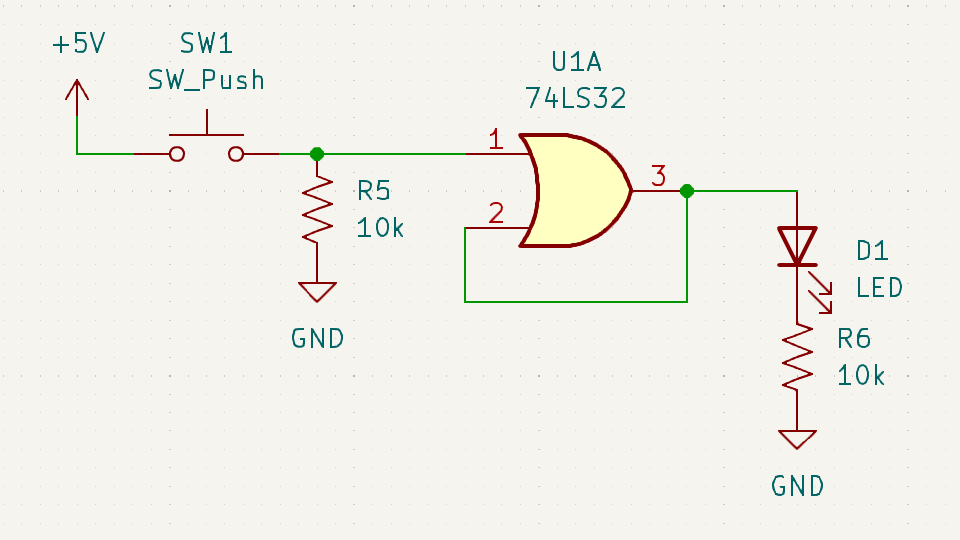
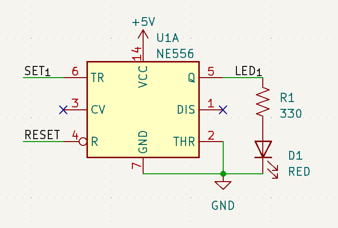
With the OR-based concept eliminated since I didn’t have the chips, I looked for a suitable replacement from my inventory of parts - of course it came in the form of a 555 timer! (Well, I actually had two 556 chips that acted as four 555s, anyways…) I could configure them to act as RS flip flops (Reset-Set), so when a button was pressed they would be set (illuminating the LED) and would ignore further presses until reset using the reset switch. This was certainly more reliable than relying on resetting the power entirely to the chips to reset them, as was the case for the OR-based idea.
Combining the goal/LED signals to determine if they were all met was done simply using a 74LS08 quad 2-input AND chip. Luckily this chip was properly identified on the bag I bought it in so no surprizes were found here.
Generating the flashing for the final LED was done using the last of the four available timers across my two 556 chips configured to run in astable mode. The “negative” logic of the timers worked well in this project since it meant that the AND generated final signal was used as the reset signal for this timer enabling it when it went high, no need for an inverter or funky hack. This logic also explains why the buttons pull down rather than up to set the flip flops.

Assembly
As I was finalizing the schematic, I had Bennett begin his hunt for the parts of his desire from my scrap bin. He found and desoldered some buttons and LEDs he liked and we ended up using for the project. All the chips and passives used were ones I had sitting in my toolbox waiting to get used. Other than using exclusively through-hole parts, the main challenge for us was the use of an (ancient) perforated board as the basis of our circuit which was something I hadn’t really done since I got into electronics with my entry fob clone.
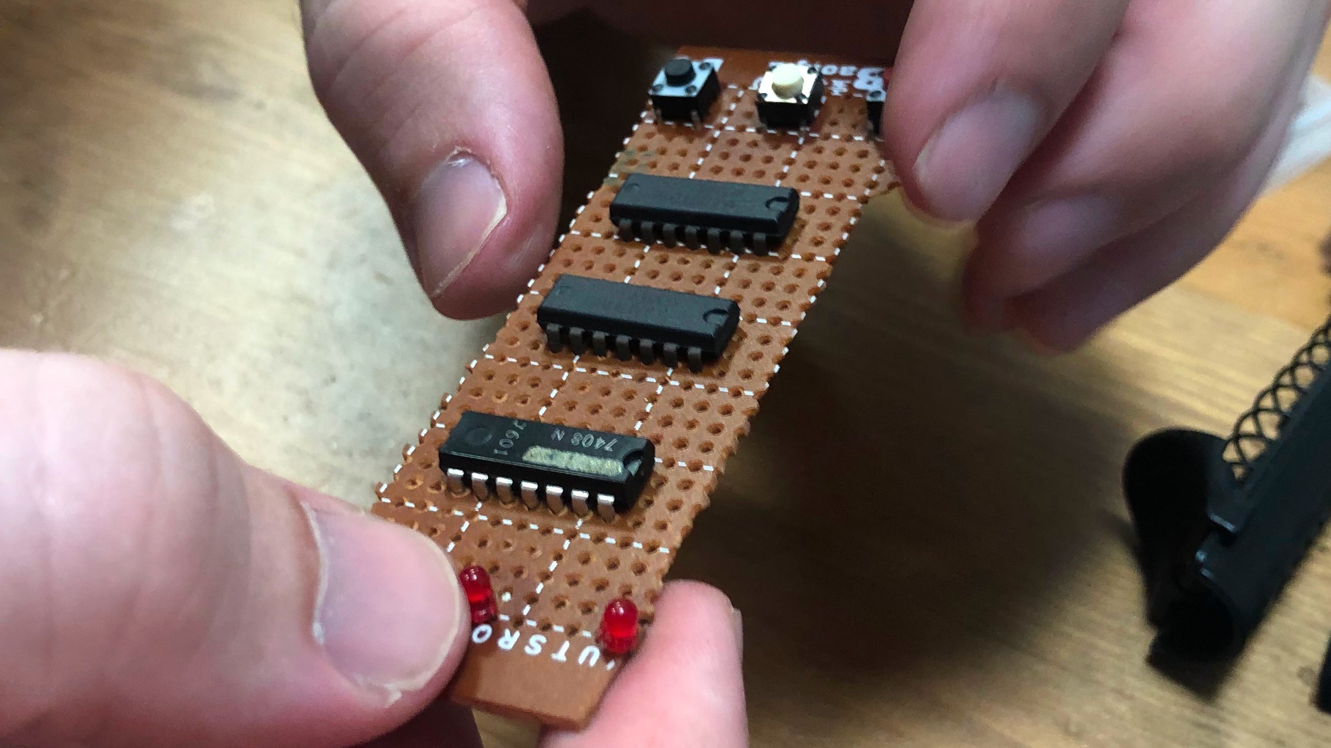
It started with an initial placement of all of our main components of interest to get a sense of the layout. Once this was decided Bennett began soldering to lock them all into place. Note: the reset buttons and power jack were meant to be off-board so they could placed to better fit their final enclosure.
Soldering was largely handled by Bennett putting wires between points I indicated to him. In retrospect the lengths I provided him were excessively long, which meant that they kept getting bumped into. The protoboard used quickly began to reveal its age when the solder failed to wet the pads since I forgot to sand off the oxide prior to us starting and some pads were lifted entirely when heated. However we carried forward and eventually completed a first pass of the circuit.
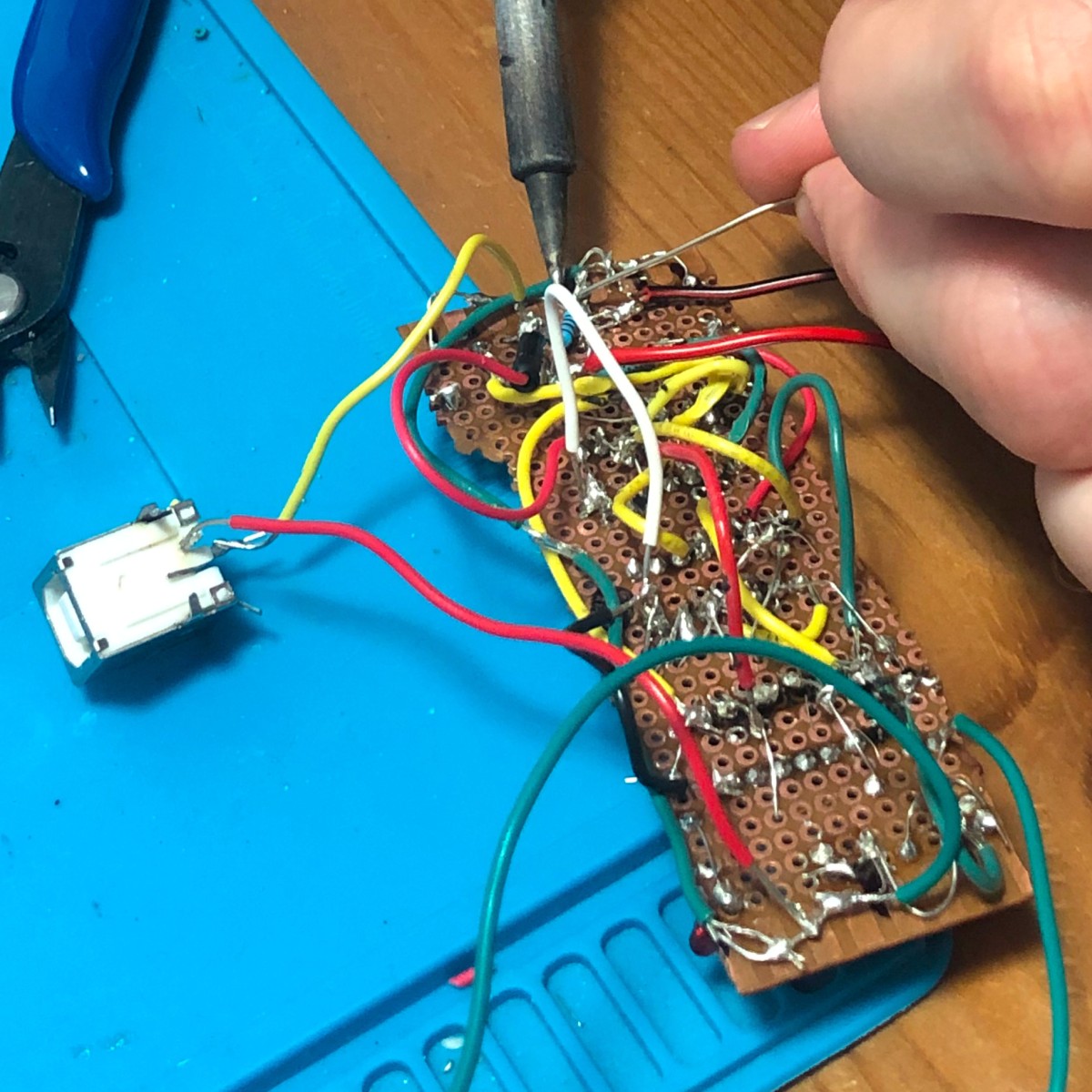
As you can see, it is quite the rat’s nest of wiring, and it obviously didn’t work properly on the first try, nor on any of the immediately following ones until the tenth or so. Most of the issues were related to connections either missing or being made where they weren’t meant to be due to wiring mistakes or solder bridges. There were two button related issues: one was installed 90° off into the board so the connections had to be adjusted, the other was that the original reset button was “normally-closed” whereas most other buttons are “normally-open” and my design expected that, so we ended up replacing it with a different switch that was harvested.
With me handling some of the more difficult soldering in this closing stage, the board was eventually completed and the schematic was updated to reflect the “as-built” state to include the last-minute modifications we made.
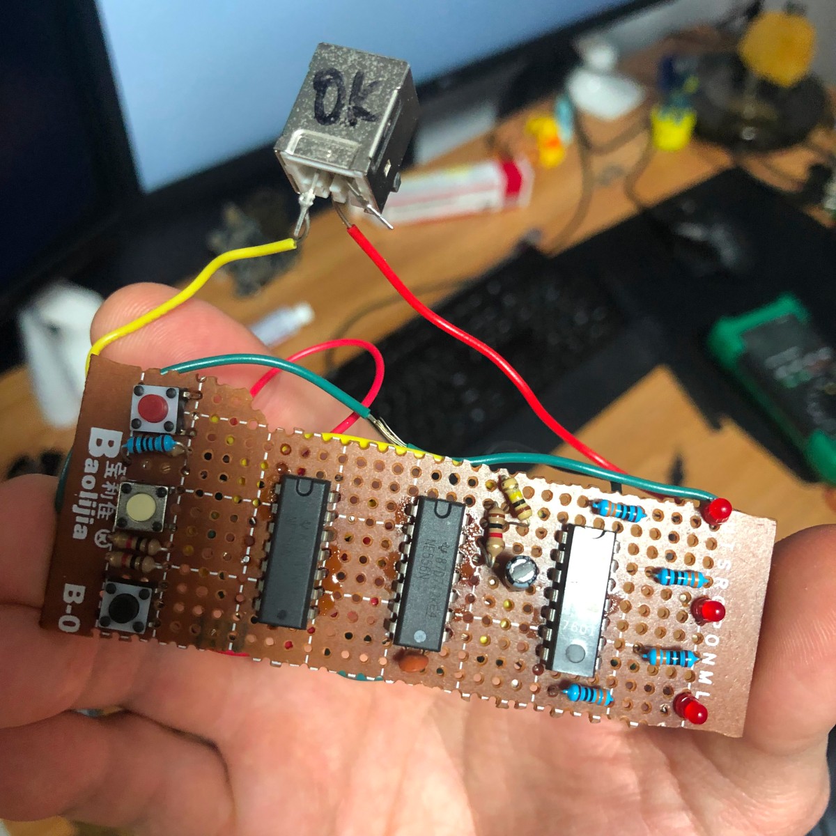
Unfortunately the final LED blinks much faster than expected but we decided against trying to fix it and risking further complications as a result. I assume this is due to some parasitic resistances affecting the feedback for the timer responsible for the blinking.
Outro
We managed to complete the board and had it working to a level satisfactory for Bennett in time for him to take home. Since then he’s built a nice little enclosure out of Lego and is using it regularly to keep himself on track. I’ve even joined in on the idea of a weekly roster of goals!
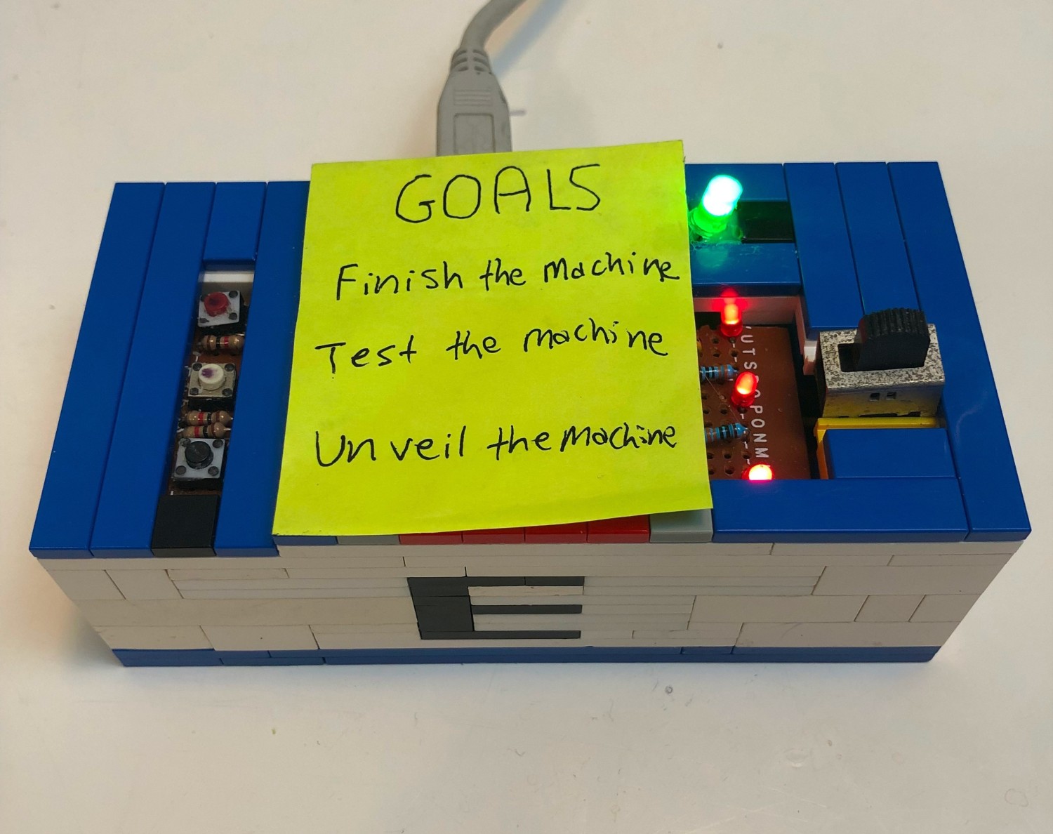
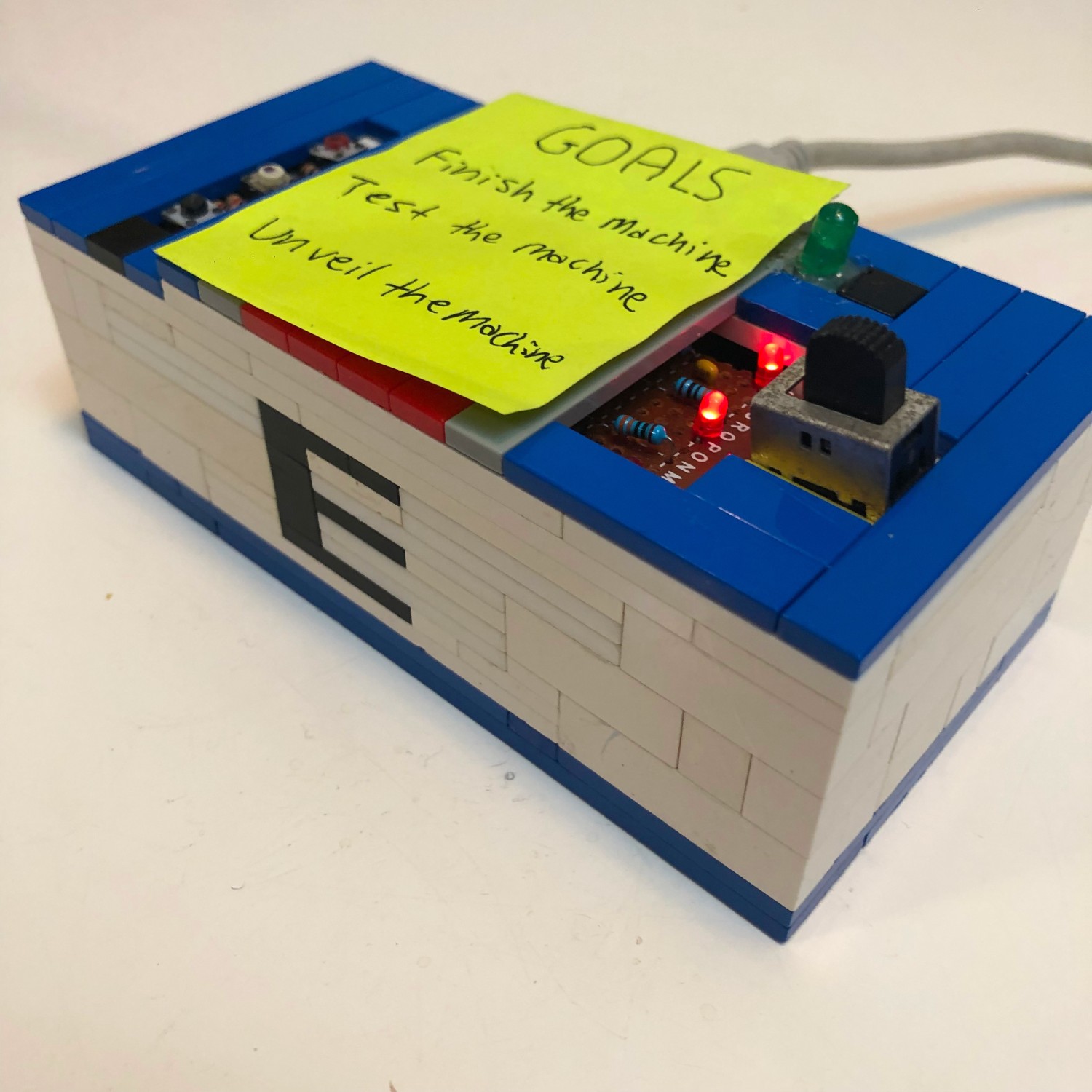
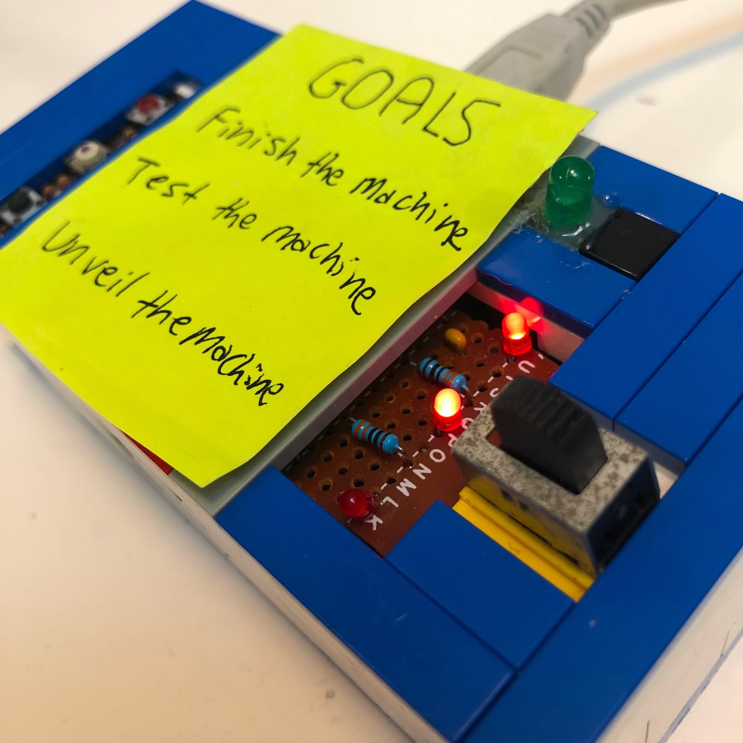
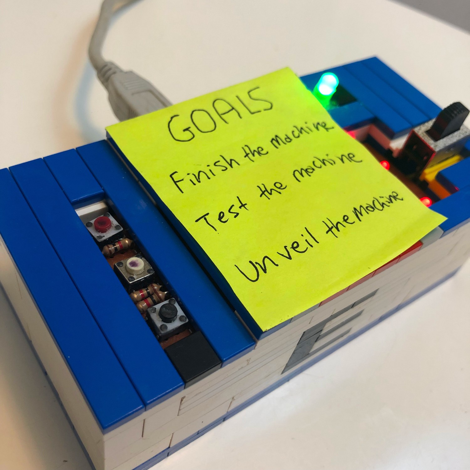
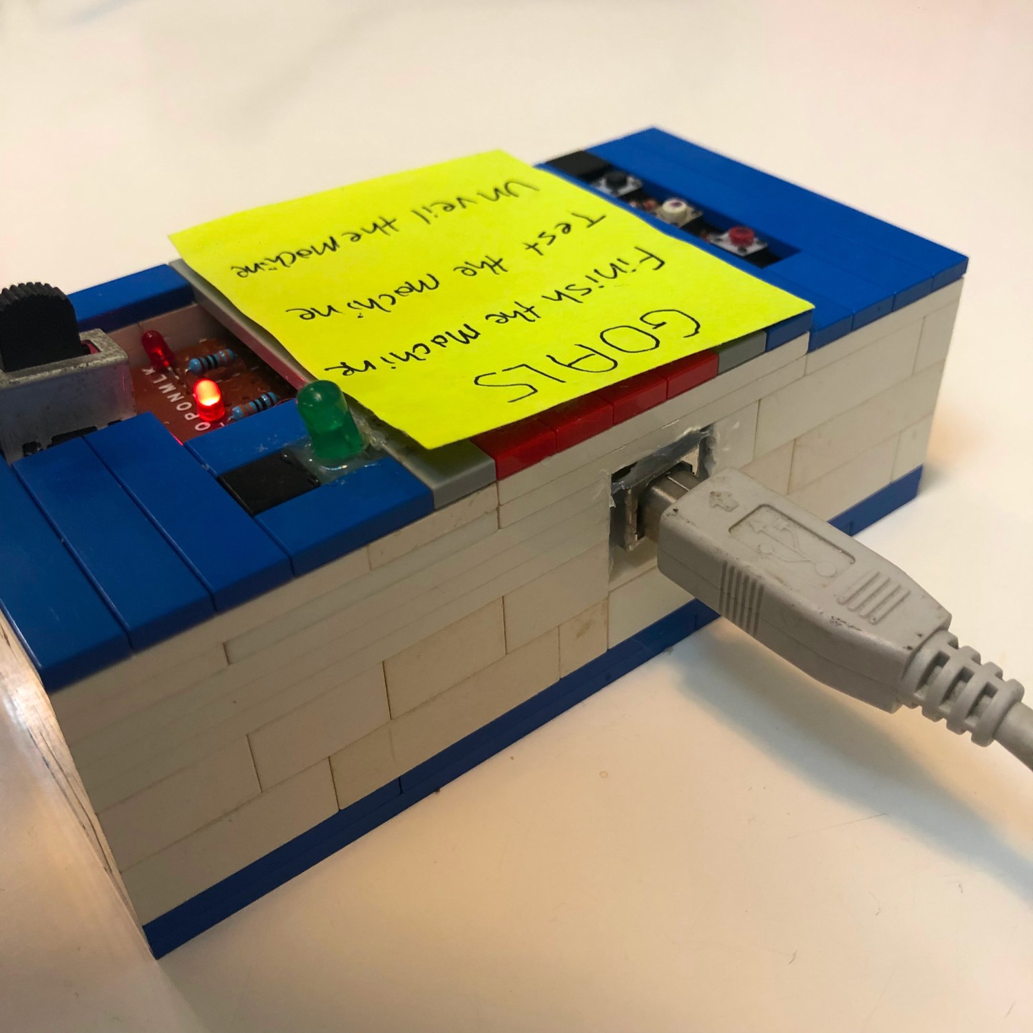
Overall probably definitely the best designed enclosure for one of my electronics projects thus far.
I’ve made a preliminary circuit board for the Edit Machine and it’s included in the project repository. I will ask Bennett for feedback on the form factor before I commit to any production, not that I’m sure I’ll ever have these printed since that would go against the original ethos behind a major characteristic of this project.