Entry Fob Replication
Table of Contents
Overview
I was curious to see how the entry system worked in the condo I was living in during my second year of studies, so I decided to see how the entry fob I was given worked (ideally in a non-destructive way). After taking it apart it became apparent it was a glorified TV remote so I set about replicating it with hobbyist equipment.
Requirements
- Understand how the entry fob communicates with the security system
- NON-DESTRUCTIVELY! I needed to return my original fob in working condition.
- Replicate the fob if reasonably possible
Objectives
- Spoof access to other floors (fobs only allowed access to certain floors)
Takeaways
Some systems are simpler than you would have expected. Case and point, the fob’s method of communicating to the building.
Having the right tools makes the difference. When trying to catch the fob’s output signal I originally was trying to use an Arduino as a rudimentary oscilloscope as I did not have access to one of my own at the time. I later used one on campus. This caused issues for few reasons:
- It wasn’t fast enough. It could only sample and broadcast a value a few times a millisecond, which made it hard to catch the narrow spikes
- It wasn’t regular. The time base was unclear, I just had a string of values with no times associated with them.
- It was difficult to change the window of measurement. I assumed that the signal would be very short, so I set the system up to blast data as fast as it could. It was only when I used the oscilloscope I was able to easily widen the window and see the period between pulses was wider than I anticipated.
Points of Improvement
There are a few points that I could try to address in a future version.
- Better battery mounting. Currently I don’t have a clip so I solder the battery directly to the board, this certainly damages it.
- Switch to entirely SMT. The board is half surface mount, half through hole technology, committing entirely to SMT will:
- Reduce the vertical dimensions. No leads sticking out the bottom, lower profile packages.
- Likely reduce the chance of shorts from other items in a pocket because the terminals would be smaller.
Detailed Report
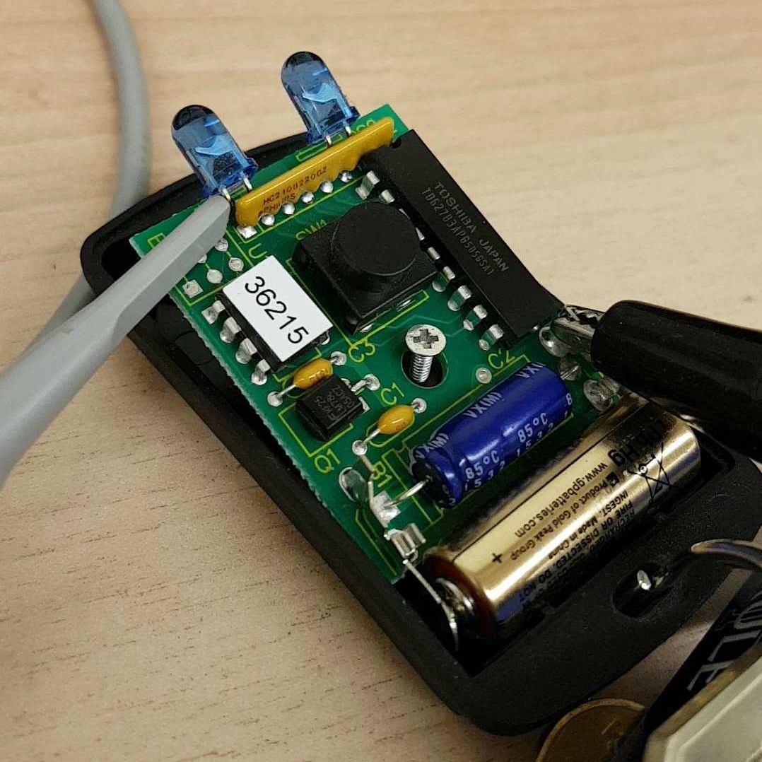
I moved into a new condo for my second year of university with two friends, and to enter the building it required the use of a fob. I was curious to see how it worked and if I could replicate it. The fob was a small black box with two bulbs sticking out the front that we had to aim at little panels and a single button to blast our entry code.
Reverse Engineering
I started by cracking it open carefully to avoid potentially damaging any delicate components that lay hidden within. With the top off, I could examine the compact and rather simple circuit contained. My main interest was in the bulbs as I wanted to see what they were. Prior to opening it up I assumed acted as a sender and the other received to allow some cross-talk with the building. However I found that they were connected in series! This meant that they could only be acting as a transmitters, thus my job of reverse engineering the protocol with the building was going to be an order of magnitude easier.
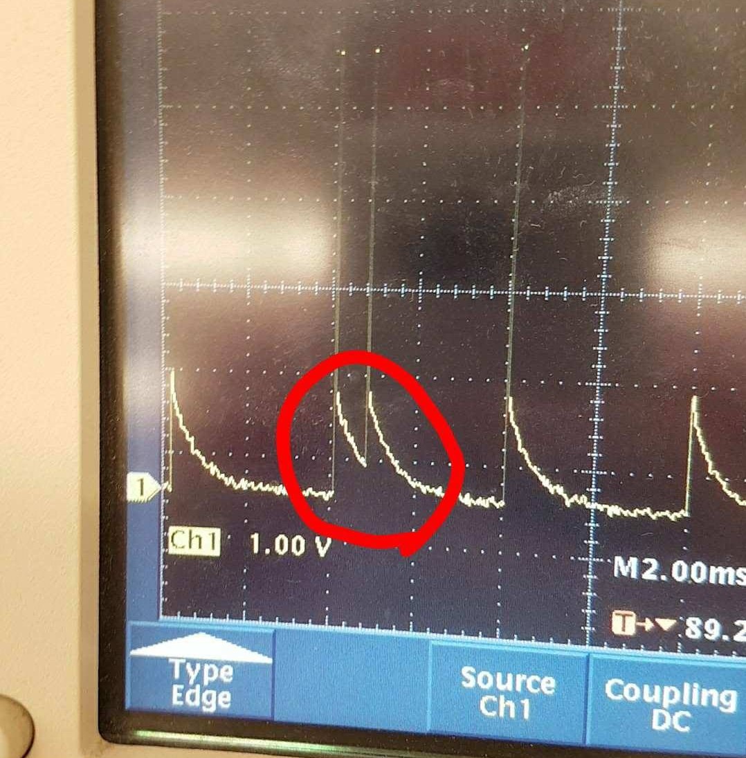
I took the board to an oscilloscope and began to probe the output to the LEDs try and find the secrets of the sent signal. I learned that the sent signal followed a consistent basic structure once the button was pressed:
- A single pulse would be sent. (Likely to awake the building’s system)
- An 80ms pause
- A 400ms string of pulses in rapid succession
- A 1000ms pause
- (Steps 3 and 4 would repeat until the button was released)
I focused on trying to find a pattern in the third part of the structure, first to convert it to some value in binary, then to see if there is any pattern between messages each time the button is pressed. The first step was easy when I noticed that in the message there were pulses every 4 ms, with some having a second pulse 0.8 ms after the first.
I decided to assign the single pulses a value of 0, and the doubles a value of 1. I downloaded the data from the oscilloscope and prepared an spreadsheet to spot spikes in the voltage readings and translate them accordingly into a string of binary.

I compared the data across five samples from my fob and found that it sent the same signal each time! I confirmed this by measuring my roommates’ fobs to see theirs acted the same, albeit with unique messages for each fob. This meant all I needed to do was was replicated this signal with a system of my own and I would have a fob clone!
Replicating the Hardware
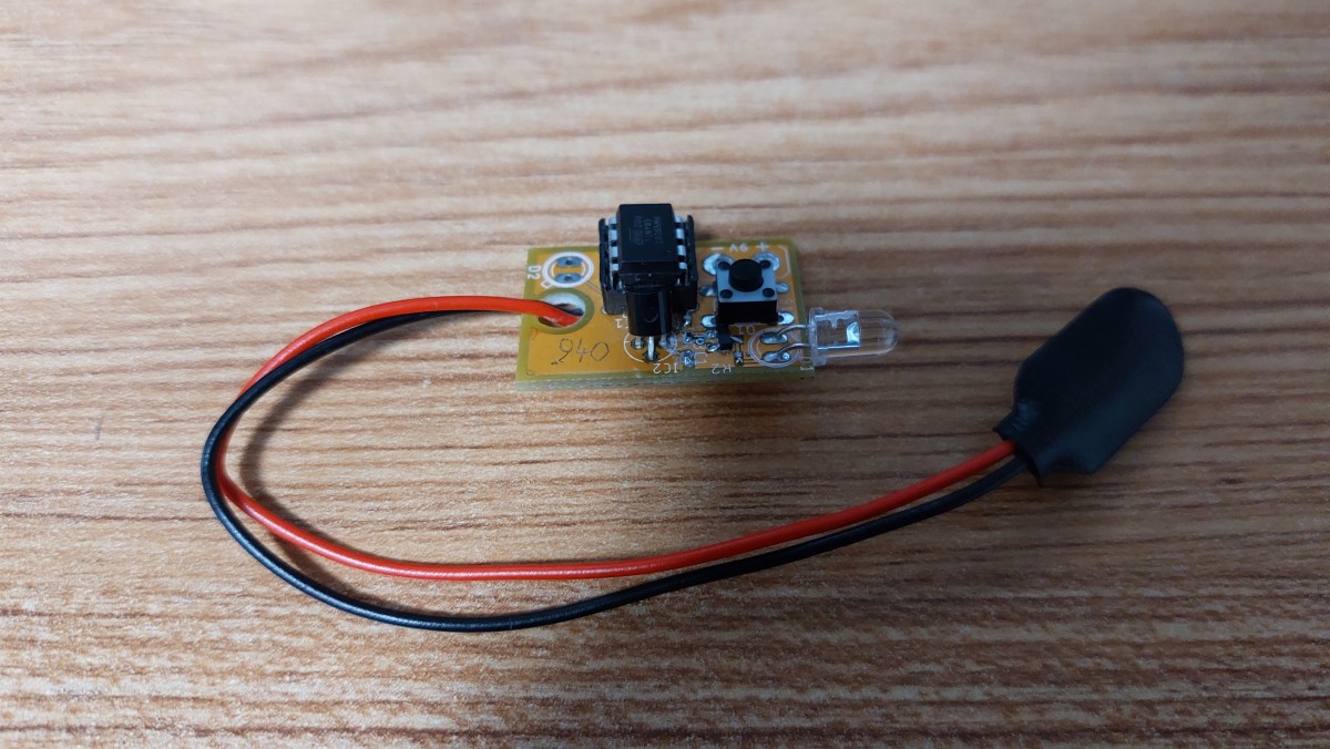
All I needed were some basic parts (microcontroller, IR LED, button, resistors, battery) and I was set. I made my first prototype that was about as crude as I could get away with and went to test in the parking garage, away from most traffic so I could test in peace without having to explain myself to, or alarming, anyone.

It was successful on the first try! Which was very convenient since to recode the Arduino would need me to return to my apartment. Obviously running around with an Arduino, battery, and breadboard taped together is nowhere near as subtle or durable a final product as I wanted for the long term, so I made more compact system, substituting the Arduino development board for an embedded ATtiny85 microcontroller with everything (except the battery) on a single protoboard.
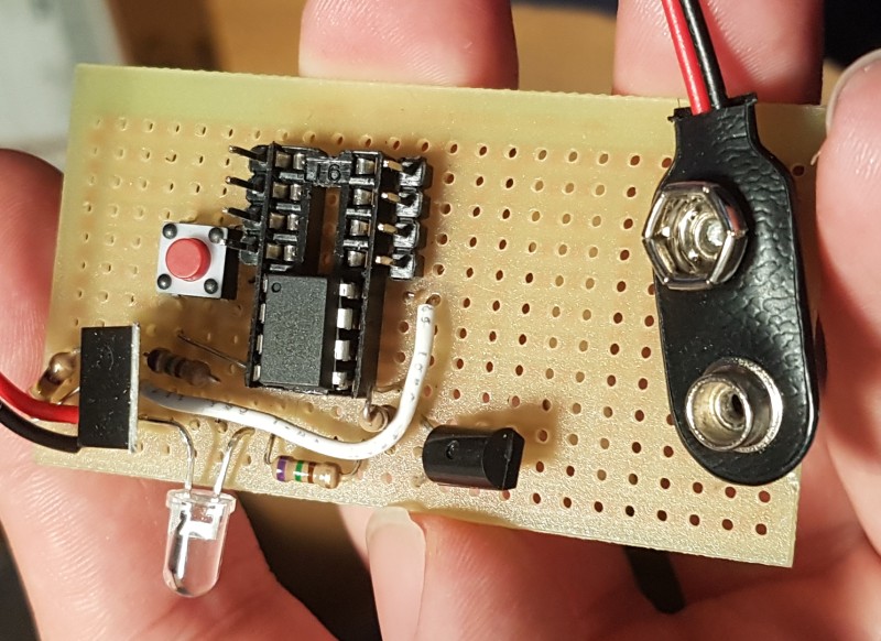
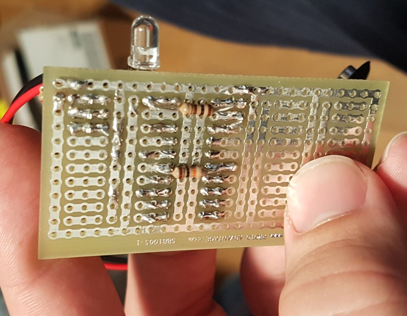
I used the protoboard from September 2017 to the end of 2019, at which point I made a custom circuit board in EAGLE, which I used from December 2019 until February 2022 when visiting!
Points of Improvement
This initial blaster had a few possible improvements I could implement:
- Use a smaller battery, mounted to the board. 9 V batteries are annoying to lug around and having it visibly dangling off the board as you use it is suspicious at best.
- Reduce power usage. Currently the system polls the button to blast, I can change this to have it instead sleep and wake up on button presses, or use the button to connect power to the entire system.
- Finally develop the “field” reprogramming feature. Sigh…
Revision
Although my previous version worked adequately, it did have some identified issues; the most apparent for me as a user was the battery. Using a 9 V battery on essentially a dongle wasn’t compact which made carrying it around a chore. So I wanted to address this in a redesign by changing the battery entirely from the 9 V to a CR12xx series battery (3 V). I did this at the start of 2022.
By changing to a CR12xx battery (I specifically used CR1220s) I was able to remove the on board voltage regulator since the 3 V it supplies can be readily used by the microcontroller. This reduced circuit complexity and size, as well as the quiescent current draw, extending battery life.
I also aimed to address the other two issues with the original PCB I made. First, I removed support for the field programming feature since I didn’t see it being useful to me, which simplified the circuit. Secondly to reduce power draw I now use the button not as an interrupt to wake the microcontroller, but instead as a power switch. This meant that ideally, the circuit would draw absolutely no current when not pressed, thus extending battery life as long as possible!
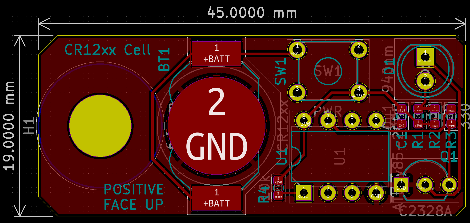
I ported the design by hand to KiCad, the resulting schematic is pretty simple. I used two 330 Ω resistors instead of a 150 Ω one since that is what I had available on hand.

I then laid out the circuit, it was a mix of both through hole and surface mount components. I was able to place all traces on the top layer, so it could be made as a single layer circuit board if I really wanted to pump these out for cheap. Its overall dimensions exceeded those of my previous version, largely to accommodate the new onboard battery.
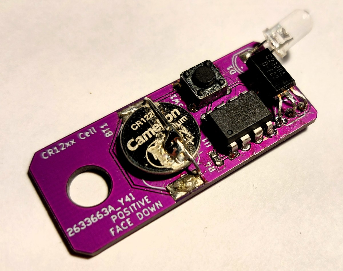
Then came the assembly, resulting in the following flashy board. Nothing to note, really a standard, mixed-technology, hand-soldering affair. My first purple board!
Assessing Performance of the Revision
The revised board worked as expected! Its range was a little shorter than the previous version likely owing to the lower supply voltage but still a respectable 50 cm or so. To get to this point I had to deal with a two minor design issues:
- I had set up the button connections incorrectly so power was never disconnected from the system. I fixed this by cutting some traces with a knife. The schematic posted has this correction included.
- I accidentally instruct users to insert the battery incorrectly on the silk screen. This has been corrected in the new layout file shown on this page and why the layout image label disagrees with the produced board’s label.
Power Draw Surprise
With the design complete and correct, it worked. However when I returned to visit my friend a week after doing my initial (successful) test, I was unable to use the fob. I had to enter like a normal person, not the hacker I wanted to be! I was devastated, so I had to find the reason for this; to both improve the design and heal my ego.
As I had expected the culprit was a drained battery, but I still don’t know exactly why. The button was supposed to prevent any current draw when not pressed, which it shouldn’t have been in my pocket. I determined a few likely causes listed below with the solutions I see to address each of them.
- The button was held pressed in my pocket by something.
- I now have the code enter deep sleep if the button is still held after a few cycles to prevent continuous draw.
- The battery was damaged/drained from being soldered repeatedly. (It was soldered and de-soldered a few times in assembly.)
- Replaced the battery with one that was only soldered once
- Long term solution would be to source a proper battery clip to not require them to be soldered in place.
- Stray conductive objects (keys) in my pockets shorted some of the leads together allowing current to flow.
- Transition to an all SMT design
We’ll see how these fixes pan out in the future!