TTC Check Board
Table of Contents
Overview
I wanted to make my previous work on getting bus predictions into a more application specific and capable system. So I took that board and tried to make it entirely embedded. Part of my motivation for this was to try and make something that would more closely resemble a product rather than a development kit.
It was my first time embedding an ESP32 module and I had to deal with a lot of its hardware quirks, especially related to programming to make it work. Makes me respect the complexity of the hardware inside it but also made me yearn for simpler programming experiences I’ve had with STM32 or AVR microcontrollers.
Once my hardware situation was settled, I was able to port my code over to this new configuration and also adapt it to the new API system used by the TTC since mid-2021.
Overall I am quite happy with it now that its working and I have made good use of it to fetch bus times. Even if 90% of its use is just me using it just to see it work. As always though, there are certain ways I can see myself improving this if I choose to come back and work on this some more.
Requirements
- Embed an ESP32 into the board with all supporting hardware
- Connect to WiFi to fetch bus arrival times
- Sort and show the next four predictions on an LED display
Objectives
- Allow for easy reprogramming
- Improve user setup experience
Takeaways
ESP32 modules are not easy to program compared to other more traditional microcontrollers, I feel this has to do with the fact that they are more complicated modules, rather than just a single unit.
Using debugging messages is vital. Especially for tracing back complicated issues as was the case with my SSL communication. Once I learned about the debugging message system built into the ESP32 core it made a massive difference for me, I was much faster at solving issues.
Detailed Report
So I had previously made a board for the purpose of checking the bus arrival times for the stops around my apartment. That board wasn’t really a full embedded project since it was essentially just a bit of hardware that an ESP32 development board was seated into, so I really wanted to make a more complete board with everything on it. To add to this, one of my former roommates borrowed the ESP32 I used for a project of their own and accidentally damaged it. They did buy a replacement, but unlike Arduino boards, ESP32 headers are not standardized and thus the replacement ESP32 board could not be seated in the original board.
So over the pandemic I didn’t actually get to use the old one much and with me starting to begin heading out more I decided to try and get some display back online. I figured this was the perfect excuse to make a new board to improve on the previous one.
Although I still had the design files for the previous project, they were prepared in EAGLE and so different to what I intended to do that I decided to start again from scratch in KiCad for the design of this board.
Circuit Design
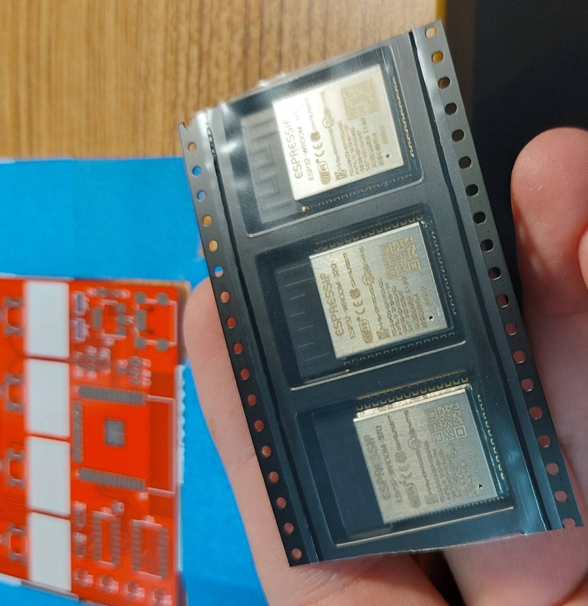
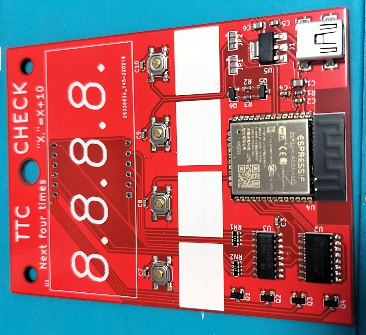
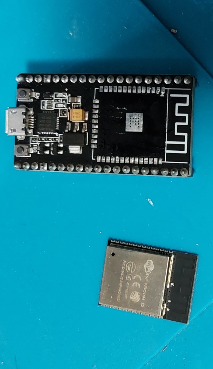
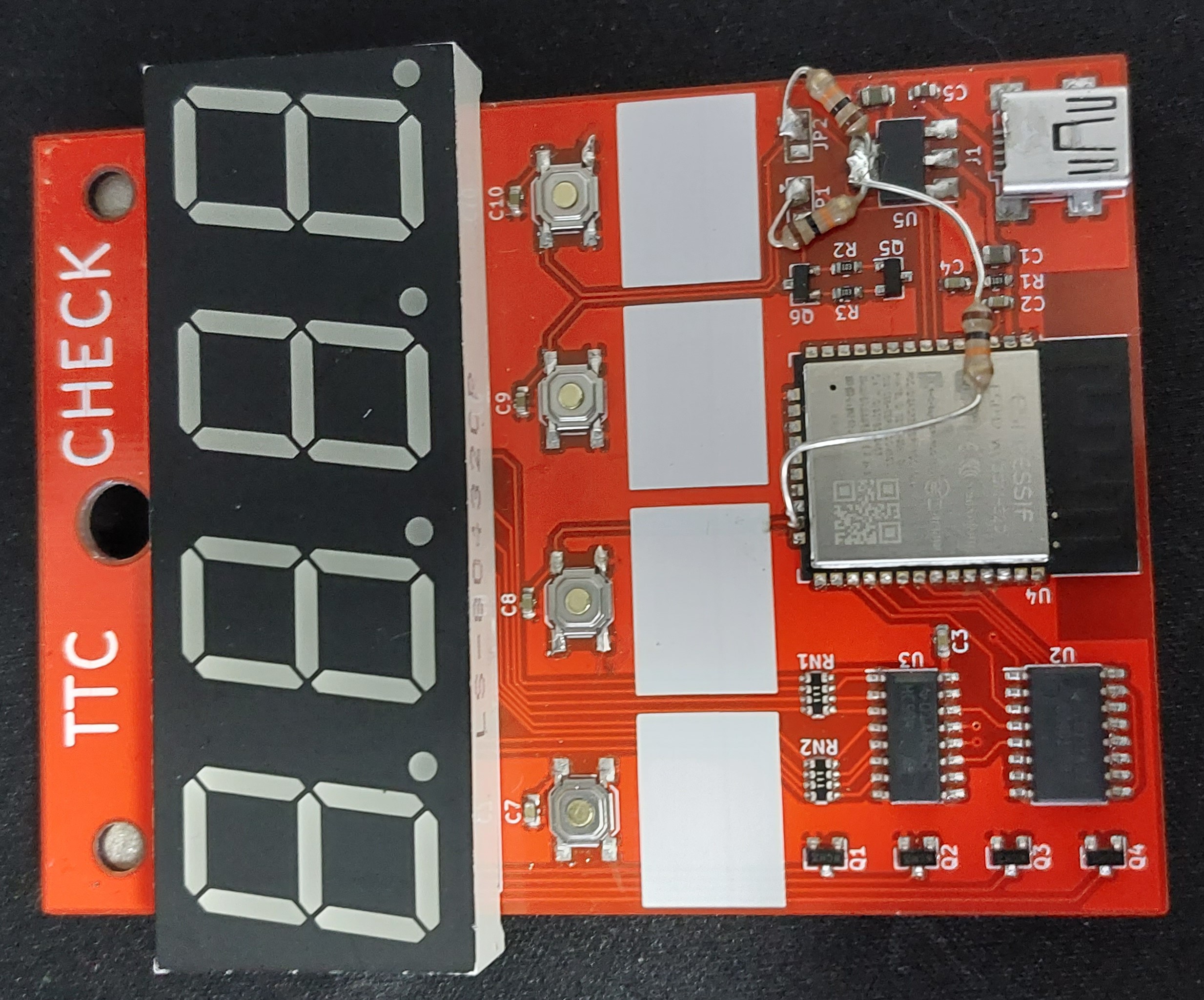
I started with the circuit design. At the heart of it the system is the ESP32 module, specifically an ESP32-WROOM-32D. This module provides a microcontroller with a bunch of flash space and wireless communication features (Bluetooth and WiFi) along with an on-board antenna for communication. To program the ESP32, serial communication is used along with a special reset circuit taken from their reference design for “auto-programming”.
Other than the ESP32 and its programming circuitry, there is the hardware for user input (buttons) and output (display). The buttons are connected to the GPIO pins and use internal internal pull up resistors on all the pins (sike). The display system is a bit more complicated, it uses a shift register to drive the segments of each digit so more current is available than if the ESP32 directly drive them itself, however this shift register is operating on the 5 V supply so a level shifter is included in the design for safe communication between the ESP32 operating at 3.3 V, and the shift register at 5V. The ESP32 however remains in direct control of the transistors to select the digit to display.
Power is supplied using standard USB with an onboard 3.3 V regulator for the ESP32.

Although not visibly reflected in the schematic I did select all my parts to be surface mount, with the exception of the display. I did this to minimize potential damage done to the walls behind when buttons are pressed.
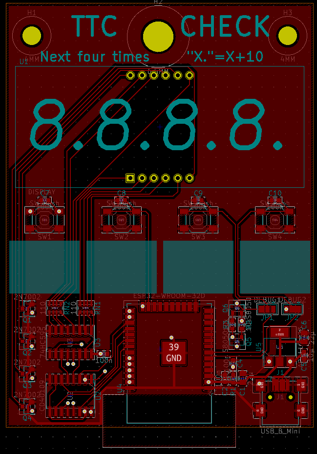
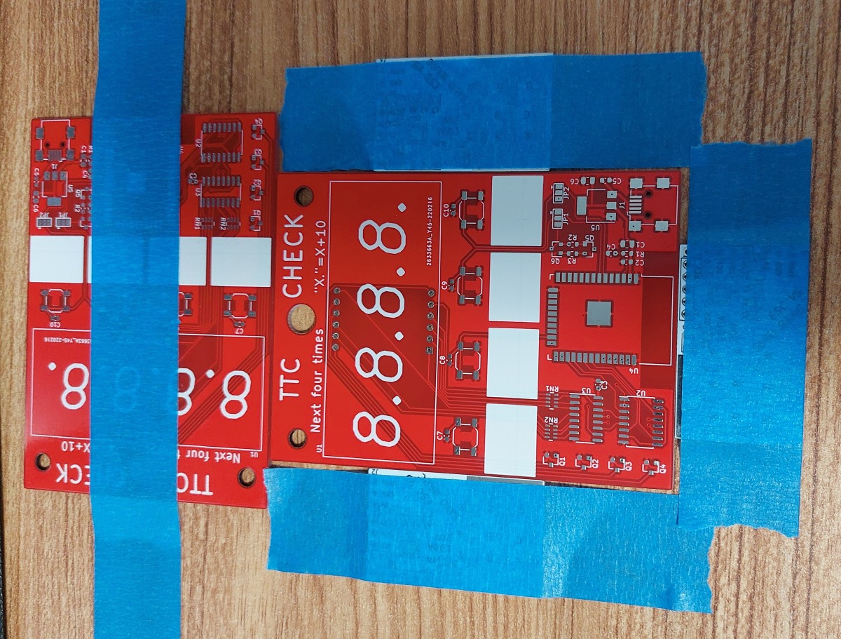
Layout
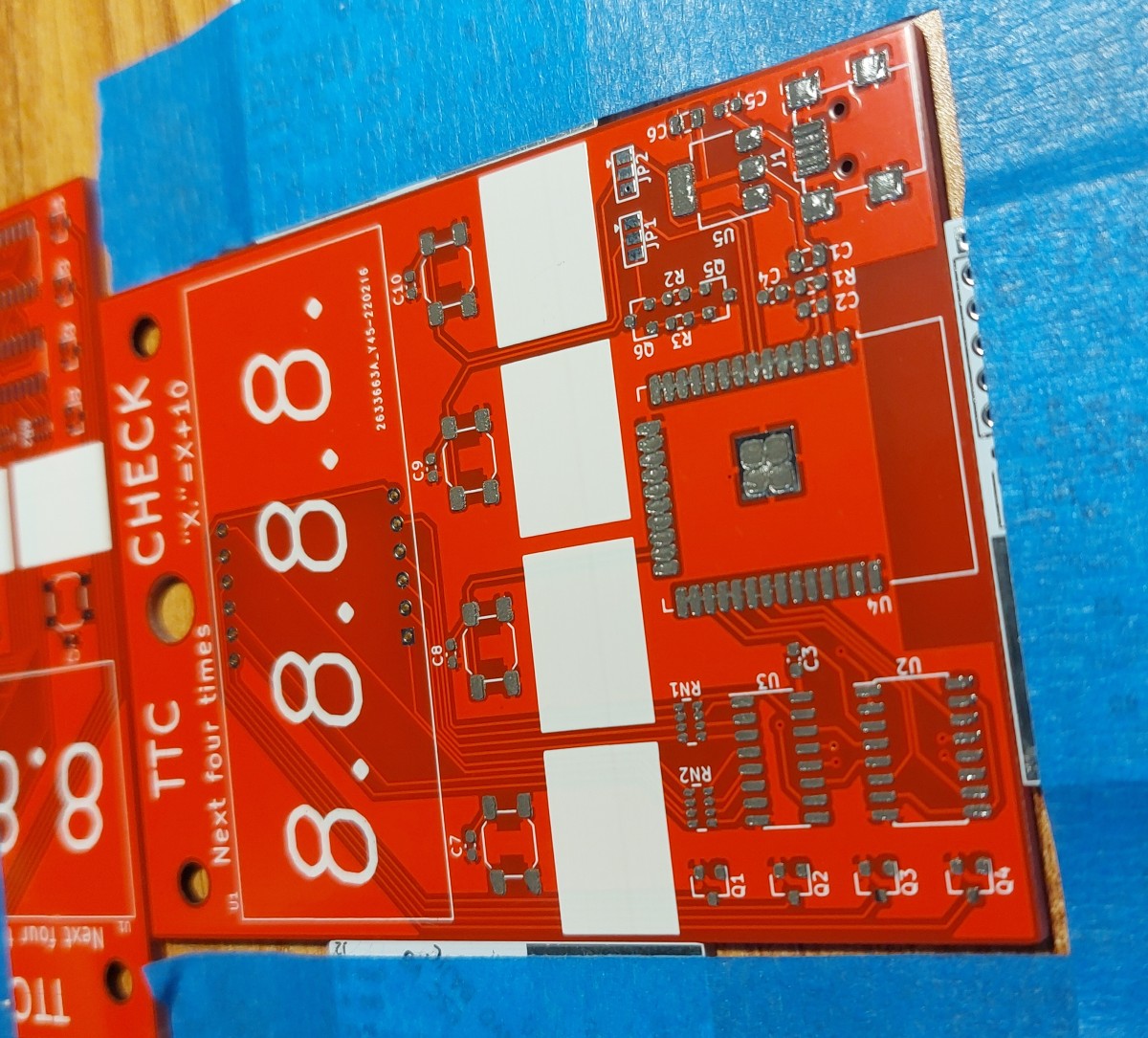
Laying out the board largely followed the layout of its predecessor. Mounting holes at the top with the display, the row of four buttons and their matching labels underneath, and then all the control electronics at the bottom.
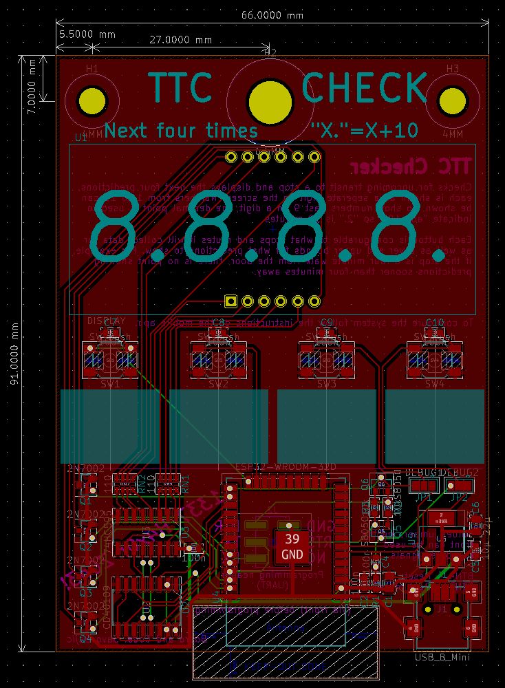
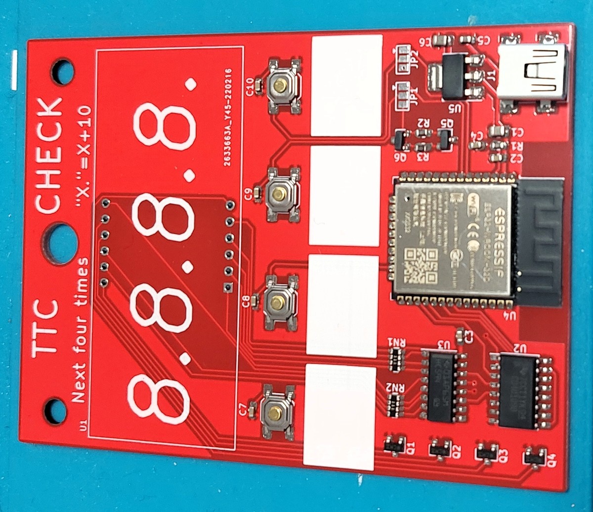
I managed to keep most of the traces on the top layer which puts them proudly on display for the users. Unlike the previous one, I tried to keep everything surface mount and on the front, so as to reduce the potential damage to any wall this will hang on. The only exception to this is the display that was through hole.
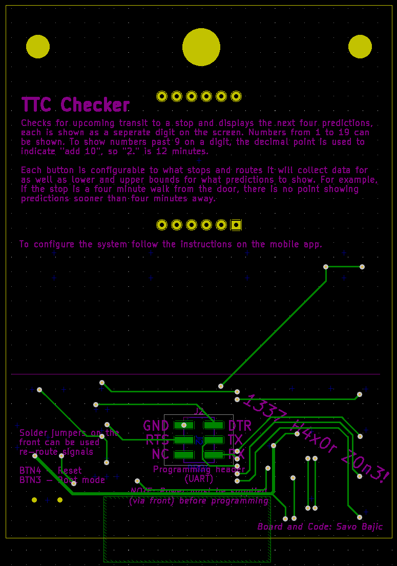
In addition to the few traces that did make it to the bottom, the programming interface is here. Other than the programming interface, the large vacant area at the top of the rear side is used to inform the user about the system with silkscreen notes.
With the board laid out, all I needed to do was wait for a few more projects to be ready before I actually got them made.
Assembly
I generally brush of this part of the projects since the process is generally the same, with few exceptions, project to project. This is one project that also stuck to the books, but I figure I should document it once in greater detail for those interested though.
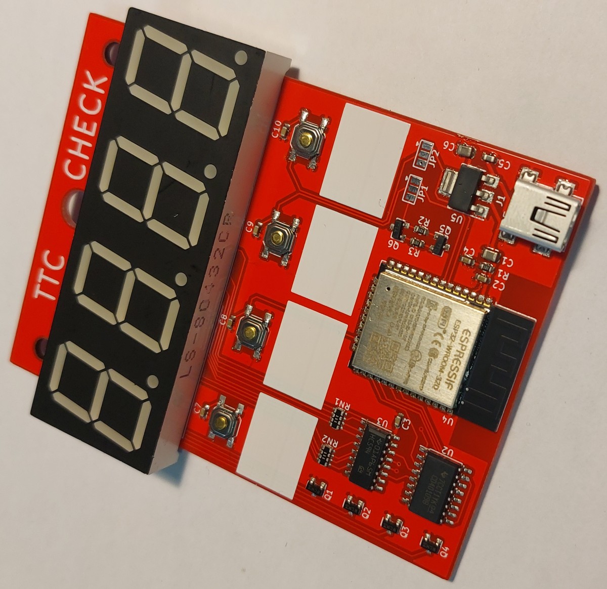
This board, like most of my recent projects, uses surface mount technology/devices (SMT/D). It does however have one through hole technology (THT) part, the display. With these mixed technology boards, I start by mounting the surface mount parts to the board.
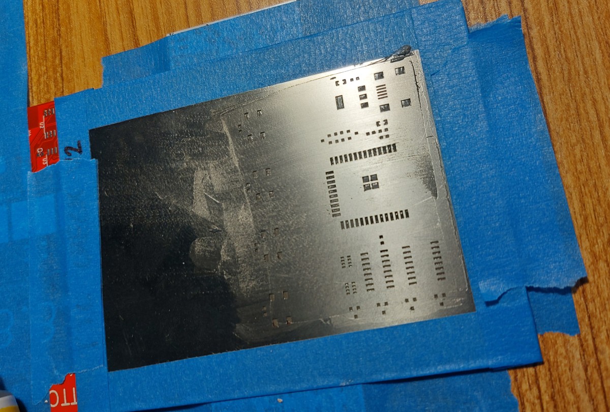
SMT parts can be soldered using the traditional soldering iron approach, but for large assemblies - and especially for automated production, stencils and paste are the way to go. As the name implies a paste is dispensed onto the board through a stencil that has openings for the pads where SMDs will go, this paste is eventually melted to solder the parts in place.
In industry, stencils are generally mounted to jigs that ensure that the openings are perfectly lined up every time and the stencil is held flat to the board. My methods would fall closer to a “cottage” industry level. I use tape and few spare PCBs to hold the board in place.
Afterwards I lower the stencil and align it so that the pads are all perfectly visible through the openings in the stencil. (I unfortunately forgot to take a picture of this step.) Once aligned, I tape the stencil in place and begin to dispense the paste on top of the stencil and spread it using an old plastic card so that all the openings have been filled.
Once satisfied with the paste I carefully remove the stencil to avoid smearing the paste that was just dispensed.
I then begin to place components. In industry they have specialized “pick and place” machines for this, but I make do with tweezers. The components generally come in reels which let me easily take them one unit at a time. I usually go from largest to smallest component size on a board since I have a habit of occasionally resting my hand on the board as I place which moves the parts unfortunate enough to find themselves underneath my hand. By saving the smallest to last I reduce my chances of losing them this way in assembly.
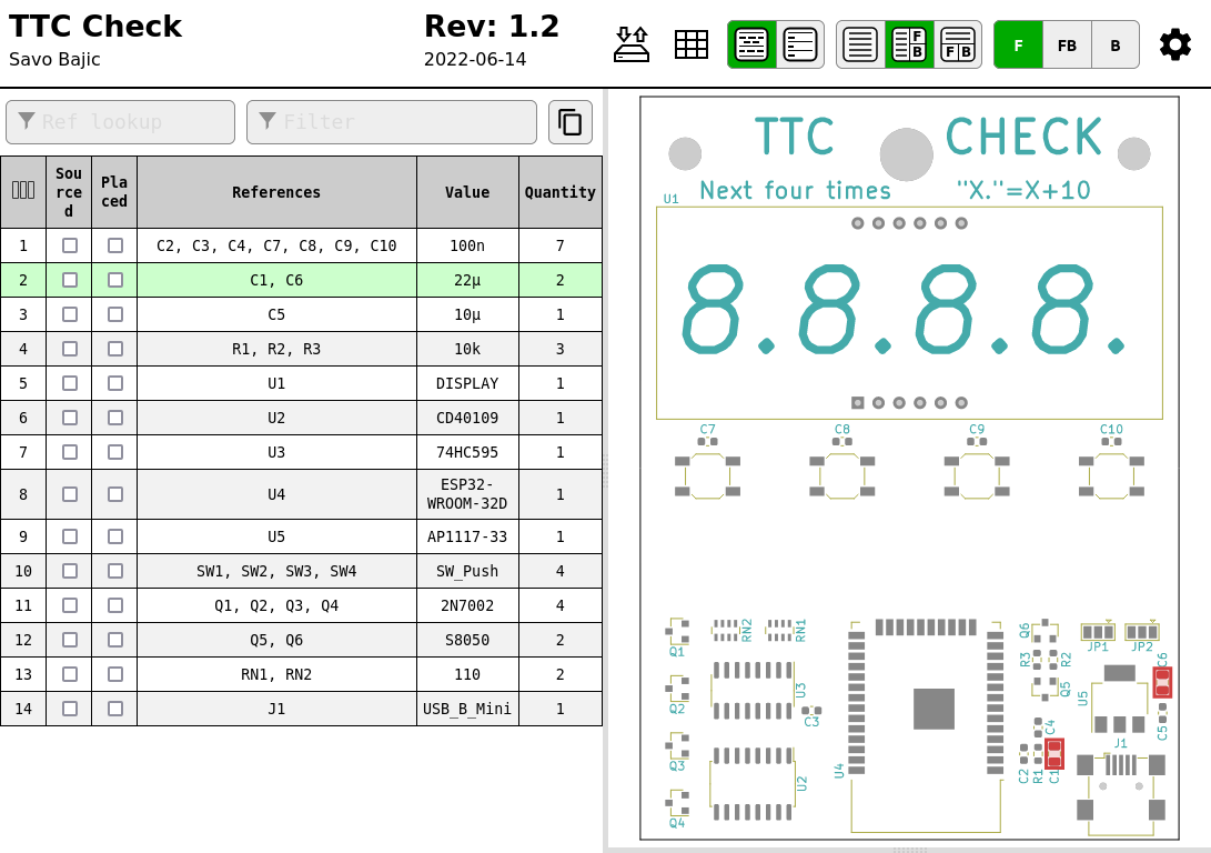
One super helpful utility I use to help with hand placing parts is the Interactive HTML BOM plugin for KiCad (it also supports EasyEDA, EAGLE, and Fusion360). It generates interactive HTML bills of materials, which not only list all the parts I need for the board but also has a board preview which shows where I need to place all of a given component when hovering over a list entry, or what list entry a particular part is when hovered over in the preview.This is honestly a life changing add-on for me since it makes it easier for me to not miss a placement for a given component and keep track of what I have and haven’t placed or sourced yet.
So I work my way though my list of components until they are all placed.
At this point I go ahead and “reflow” (melt) the paste to solder the parts in place. There are a couple ways to do this, but they generally converge on generating hot air and blowing it across the board. I use a hot a rework gun, which is essentially a small “precisely” controlled hot air gun which allows me to dial in the desired temperature and air speed. Both are important since you don’t want to heat things too much, nor do you want to blow too hard and start moving your components.
Generally I follow a two step procedure that I incrementally apply across the board. First I do a lower temperature “soak” to get the board and components up to about 120 to 140 degrees Celsius, then once I see the paste starting to get runny I crank up the heat to start melting the paste and locking parts in place. It isn’t good to apply this for long since you may damage the parts.
Once one side is done reflowing, the process would be repeated fo the other if there are surface mount parts and a stencil for it. The only difference is that there would likely be additional spare boards used to prop up the board on the corners to keep it level and not resting on the components just soldered on the one side. However this board does not have any components for the other side, so I will go to soldering the THT part(s).
Unlike SMT, hand THT assembly is much more incremental, requiring one to repeat the same few steps in batches with their parts.
These part batches are generally based on component sizes. First I place all the smallest THT components of a similar size in the board, usually bending a lead on the back to hold them in place as the board is moved or flipped. Once I have all the parts of a given size placed I flip the board and solder only one lead on each. Since all the parts are similarly sized, the flipped board will likely be resting level with the work surface and the parts will be pressed against the board making for a nice looking placement. However I can then reposition parts if I please using one hand to hold the part and the other to melt the single lead that was previously soldered. Only once I am happy with the placement of a part do I solder all its leads. Once soldered I trim excessive leads as needed.
Once all parts in a batch are soldered, I place the batch of parts slightly taller. This way it is always the actively soldered parts that are getting pressed between the board and surface which helps keep the placements nice and everything level.
However most of that didn’t matter in this case since I only had one part to solder. Took about five minutes to do including warming up my soldering iron.
With a board assembled it was time to start developing the code and testing the hardware.
Development
I was able to reuse much of my previous work with only a few alterations related to the new hardware configuration and some of the changes that had to be made accessing the API for bus predictions. Since I was reusing code from the past I continued to use the Arduino IDE and its flavour of C/C++.
Development of the system’s firmware and its testing took a few days, largely due to issues with programming and SSL.
Programming Issues
The first for any embedded project is to establish and verify a reliable programming method. This proved to take up the most of my time developing the code for the system, 2.5 of the four days. The ESP32 is meant to be programmed over serial so I designed my board to accommodate a serial adapter and the required auto-reset circuits needed to start the serial programming exchange. I also included solder jumpers to have the buttons three and four perform these duties manually if needed.
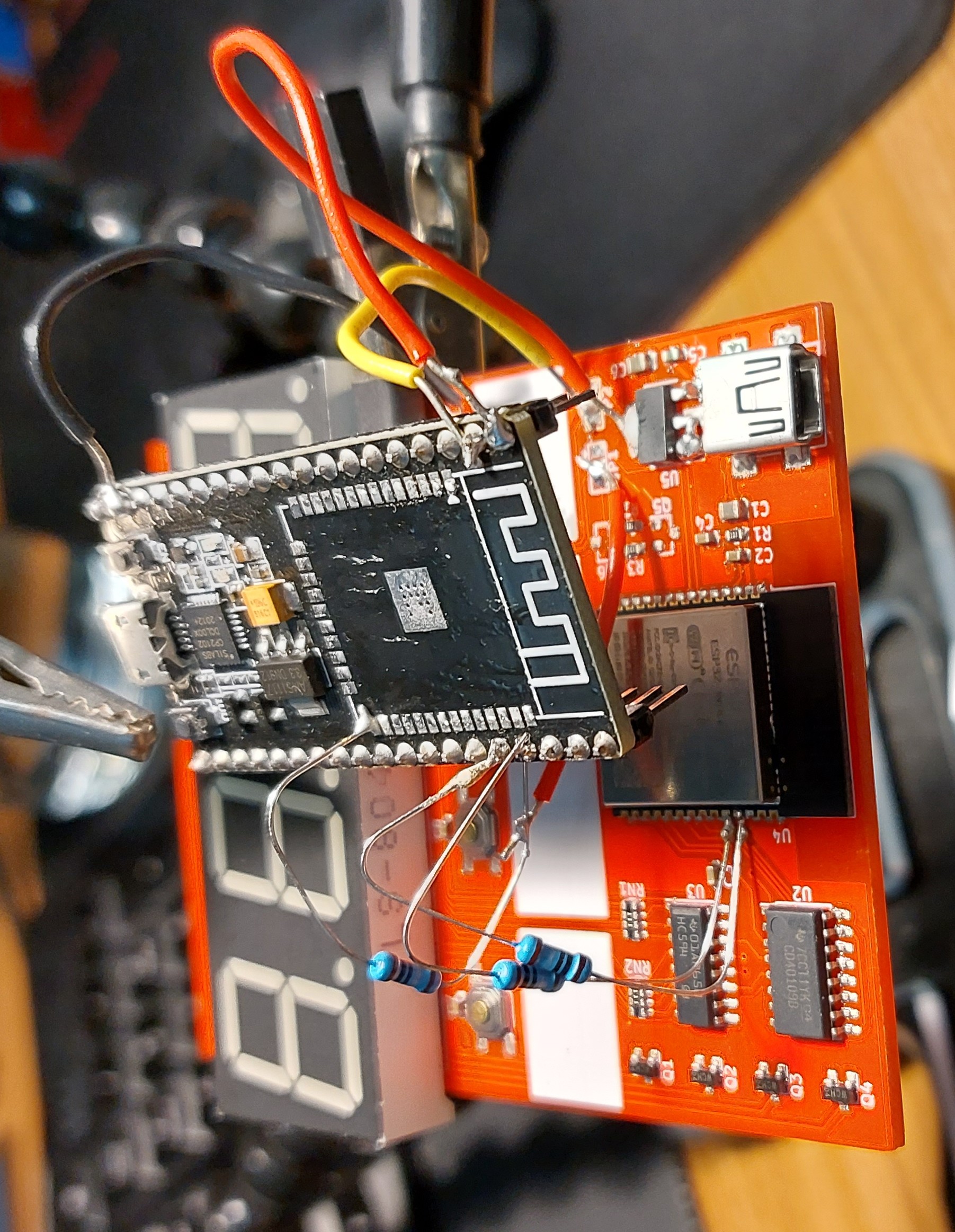
However I had issues with the system on my board, even though it followed the reference design exactly. I could occasionally get it to program but I’d always have to manually aid the process with the buttons and hope I hit them just right. I figured the issue might have to do with my auto-reset circuit and the long lead wires I used after having issues with the raccoons. After my frustration with my board reach a head I decided to remove the ESP32 from one of my spare development boards and wire my ESP32 in its place.
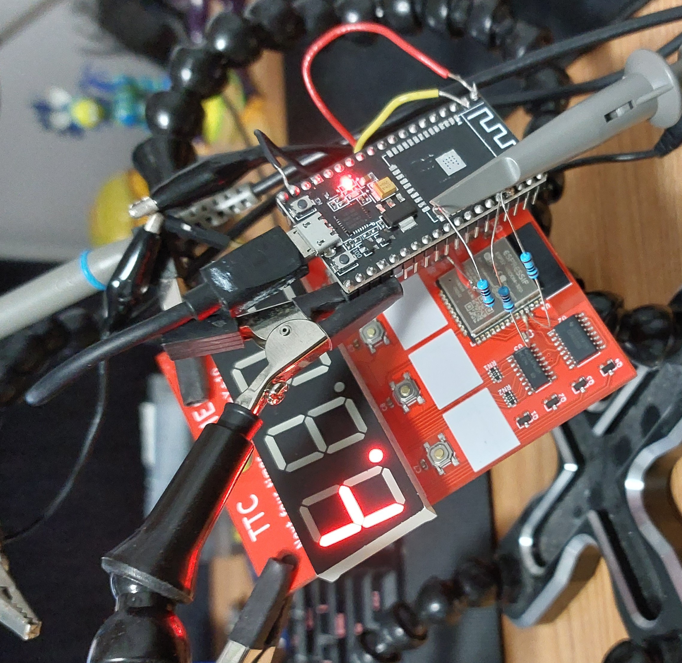
I used some 1 Ω resistors to form the connections I needed for programming directly to the ESP32 since my wires were a bit too thick to do it nicely. For data lines 1 Ω is negligible so it didn’t really matter. I also removed the transistor from my board’s auto-reset circuit so they wouldn’t interfere with the development board’s system. I wouldn’t say it was completely deadbugged, since the development board was still right side up, but it is pretty close.
This worked much more consistently, but still needed me to aid it manually most of the time. I used this approach to develop the display code, but once I was working with the API-related code it became tiresome to keep using the button and dealing with the instances where my button mashing failed. So I tried something new.
Over The Air (OTA) Updates/Programming
Since the ESP32 has built in WiFi capabilities, it can make use of the Arduino OTA system, allowing it to receive code over the local network. All I needed to incorporate it into my system was to include its basic structure into my sketches which wasn’t difficult since it was pretty self-contained and didn’t infringe on my other functions.
This was amazing, I didn’t expect it to be so easy. After about 10 minutes of coding I was able to upload code over WiFi without needing to press any buttons. It was also surprisingly resilient to interrupted uploads which happened a few times, I just needed to reboot the board and try re-uploading. With this in place I no longer needed to use a serial programmer (or in my case a mutilated development board) to upload code. I’ve kept this process ever since.
Although I was using WiFi to upload code to the ESP32, I did keep the development board attached until I was satisfied with all the code since it was acting as a convenient serial-to-USB converter for my debugging and development messages I depended on for my later work.
Display Code
In the previous system, the ESP32 directly drove the segments, in addition to the digit transistors. In this new system I have a shift register as an intermediate stage and so I needed to write code that would communicate with the shift register to drive the segments for a given digit. This wasn’t anything particularly new or difficult for me since I have done this many times before when using large amounts of LEDs. The only notable difference this time is that because the ESP32 runs so fast I didn’t have to both with any register level optimizations to quickly pipe out data.
Once I had my code ready, I went on to integrate it into my previous display code for the ESP32. Namely the periodic interrupt that is used to multiplex the digits.
New TTC API
The TTC was partnered with a company called Cubic and used their service called NextBus to provide predictions back when I was doing my first version of this project in early 2020. However since then Cubic released a new subscription-based service called Umo at the start of 2021 (subscription services are really the “in” thing these days eh?) and transitioned the NextBus service to a new domain as part of it May 18th, 2021.
Cubic has announced the launch of Umo, a fully integrated suite of platforms for riders, transit agencies and mobility service providers available as a subscription service. The new package of products will be available under one roof, similar to other subscription services such as Netflix or Office 365, according to those behind it.
I found this out after trying to run my code and being greeted with a response redirecting me to the new domain. This change is also mentioned in the document about accessing the data feed. The previous domain I had to connect to was “webservices.nextbus.com”, the new one is “https://retro.umoiq.com”.
So just get on with it and change the damn domain you connect to. I did, my connection was refused.
I was taken aback, so I double checked my requests were properly formatted against what the public feed document required and they were correct. I even copied them into my browser to try manually requesting data that was and it worked. After scrutinizing every detail on my browser’s requests to see what I was doing wrong on my ESP32 that it was automatically correcting for me. I found it, and in retrospect it should have been more obvious - the new domain was using SSL to make a secure connection (https://) instead of the previous one (http://). This had a few minor things that I needed to accommodate for:
- New port number. 443 instead of the previous 80
- Initializing and using a secure connection client
- Establishing a secure connection
The first issue was fixed by changing the constant used for port number.
Setting up a secure connection client was pretty simple too. Espressif has prepared libraries just for this purpose, by including <WiFiClientSecure.h>, one can use a WiFiClientSecure object in the exact same way WiFiClient is used. So all I needed to do was chenge my declaration of my client to be a secure one after including the library. That was it, just two lines changed, three if you include the previous fix for port number too. Oh boy did I not know the challenges I had set up for myself ahead.
In the end, getting a secure connection to work doesn’t require much additional work. The more proper method involves setting the CA certificate to the root CA certificate of the server you want to reach before connecting. One can easily get this information for any given website online and copy it into your code as a constant, then simply pass it into secureClient.setCACert(). Since I am only connecting to one server, I need to only set this once in my code. The other method that worked for me, that I don’t condone as proper was simply using secureClient.setInsecure() to forgo any security checks in communication.
My problem with it was getting to that point of understanding, I did a fair amount of debugging when I first tried connecting with the secure client and my connections were refused according to the error messages. So I assumed something was wrong with the handshake or protocol and the server was refusing my ESP32. It was only once I learned about the debug logs and used them that I found my issue was that my ESP32 was refusing to even try making the connection to the server because I had failed to supply it with some security validating credentials and wasn’t willing to accept an insecure connection (hence why secureClient.setInsecure() was a viable solution).
I feel this wouldn’t have been an issue if the examples or library were more explicit about the need for these credentials for a secure connection to be made. Alas, hindsight is 20/20 and hopefully others don’t make my mistake of not bothering with CA certificates at first.
With the connection made securely, my system worked just fine. I didn’t need to make any changes to how I made requests from my previous code nor how I handled them.
Debug Messages
Although not a feature I developed; learning about, and then using the built in core debug messages was immensely helpful for me especially when I was working on getting the new secure connection system working.
These were functions in the form of log_X() where X was some debug level, e.g. “i” for “info”. These functions would largely act like a typical printf(), which would be output over serial. However these functions had some additional behaviours:
- They would only be active and included in compiled code based on the debug level at compilation.
- Error < Warning < Information < Debug < Verbose
- Messages would be shown if their level was met or passed.
- E.g. Warnings will appear at verbose level compilation, but verbose messages will not appear for warning level compilations.
- Their message would be automatically preceded by information about the message itself:
- Message level
- File name of where the code is from
- Line number of the log within the file
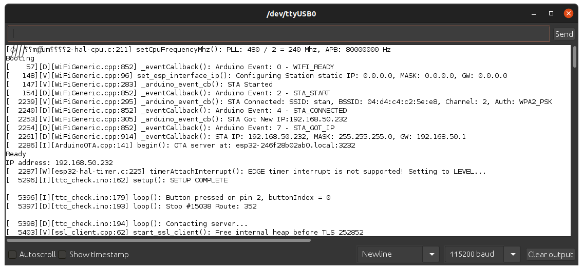
For example log_d("Contacting server..."); would print the message “Contacting server…” preceded by the run time of [ 24], flag of [D] for debug level message, [ttc_check.ino:194] for the file name and then line number then the function name. The overall result being:
[ 24] [D] [ttc_check.ino:194] loop(): Contacting server…
Only if the core debug level was set to “debug” or lower during compilation though! If not, it wouldn’t even be included in the compiled code. Saving space and time for when actually deployed.
This feature helped me track down my problems with the secure connection libraries. I implemented them into my own code since I found them much more elegant than the #define DEBUG_MODE system I was using previously. They reduced my code complexity while also providing more information and seamlessly accounted for and adjusted by my compilation settings.
Custom Data Parsing
As I completed my previous version I wrote my own code to parse the XML returned by the API, so I no longer depended on the TinyXML library to get data from the responses. My function for this is pretty simple, it simply reads in the response string character by character and if a match is found for the keyword of “minutes=”, then I record the next two characters and convert to an integer using atoi(). This integer is then inserted into the prediction list as appropriate.
The cycle continues until the end of the response is reached.
Pull Up Issues
Once I was sure that I was collecting the bus data correctly and my displays were fine, I figured it was time to switch my buttons 3 and 4 which had been used for rebooting the ESP32 and putting it into programming mode, back to their main purpose as additional user inputs and calling it a day. Their internal pull ups would work like they were for buttons 1 and 2 until that point (I was using them to trigger prediction collection as a user would for testing code) and they would just work.
…
GPIO stands for “General Purpose Input/Output”, and is meant to indicate a pin can be used for general purpose inputs or outputs. This seems to have not made it to Espressif who make the ESP32 since they labelled GPIO 34 and 35 as such, which I used for buttons 3 and 4, when they are in fact only input, lacking internal pull ups! So this explicitly needed me to add my own external pull up resistors.
For some reason the GPIO used for button 2 (GPIO15) has an internal pull up but it was not working well so I also added an external pull up for that line and it worked correctly again too.
These luckily didn’t take long to diagnose and can be easily fixed with a future hardware revision to include an external pull up on each button. I just lost some time trying to find a document from Espressif to confirm that GPIO 34 and 35 were indeed only inputs.
With the buttons complete, the board was ready to go!
Future Plans
I am happy with what I’ve managed to achieve with this project. I always press a button whenever I pass it at home just to watch it work, even if I am going nowhere anytime soon.
Although the system is feature complete for what I needed from it, there a few things I have taken note as things I could improve going forward.
Hardware Revision
Firstly I can make a new hardware revision to address my issues with the board I currently have. For now I have added my desired changes as a set of notes in the margins so I can implement them when I get around to it. The main issues I want to address with this future revision would be the pull-up resistors for all buttons and moving to some SMT displays.

Software Features
Part of the reason I wanted to make this in the first place was to try my hand at making a complete “product” for some casual users. Something people that don’t have serial to USB adapters at home could use. This mostly comes from having nice software and user experience. To reach this level of user experience there are a few features I would like to code in the future. They all largely come down to allowing the user to tailor their experience without needing to edit or flash new firmware to their devices.
- Using Bluetooth to configure WiFi credentials
- Using some (basic) graphical interface to set up their buttons
- Perhaps a self-hosted web-page
- Use flash to store use configuration
- Highlight express buses
- Flash an “E” alternating with the time